Download
1 / 9
90 likes | 265 Views
Conceptual Design of a Compact Fizeau Interferometer. Neng-hong Zhu, Xin-yang Chen Shanghai Astronomical Observatory 2014/11/2. Background & Goal. Dream: Optical long baseline interferometer based in space Reality: Optical interferometry of China is just in inital stage

E N D
Conceptual Design of a Compact Fizeau Interferometer Neng-hong Zhu, Xin-yang Chen Shanghai Astronomical Observatory 2014/11/2
Background & Goal • Dream: Optical long baseline interferometer based in space • Reality: Optical interferometry of China is just in inital stage + limited money • Option: Compact Fizeau Space Interferometer • short baseline • direct instantaneous imaging • small scale • Step 1: • gound prototype with diameter equivalent to 1m • Step 2: • Fizeau space Interferometer with diameter equivalent to 2~4m • future: • longer baseline & more elements...
Array configuration α=10° α=0° α=20° α=30° Geometric Array Modulation Transfer Function: MTF=|FT(PSF)|
Beam combining errors (1/2) • PSF vs. piston error piston=-0.4λ piston=-0.2λ piston=0.2λ piston=0.4λ MTF vs. piston Strehl Ratio vs. piston SR≥0.9 -----> piston P-V≤0.1λ [Cao Fang, et al, 2008]
Beam combining errors (2/2) X tip=0 X tip=0.1λ X tip=0.2λ X tip=0.3λ • PSF vs. tip/tilt error Y tilt=0 Y tilt=0.1λ Y tilt=0.2λ Y tilt=0.3λ MTF vs. tip/tilt Strel Ratio vs. tip/tilt SR≥0.9 -----> tip/tilt P-V≤0.055λ≈0.3" [Cao Fang, et al, 2008] (a)Y Tilt Error=0 (b)Y Tilt Error=0.1λ (c)Y Tilt Error=0.2λ (d) Y Tilt Error=0.3λ
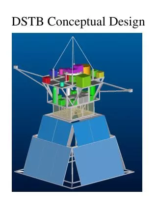
Spec. of the ground prototype • Y-4 array -----> (1) high stability due to symmetric structure (2) optimal MTF (3) tubes modulization • common mounting -----> without optical delay line for compensating outer OPD • C-shape board & triangle flatform -----> high stiffness & resonance freq. • wide FOV ~ ±2 ' • Direct Drive -----> no backlash, high tracking accuracy ~ RMS:0.01"(Dec=45°)
Optics design sub-telescope optics folding & combiner optics confusion circle Φ≤ 0.7"
Challenge • How to measure and eliminate co-phasing errors between sub-telescopes? • pyramid wavefront sensor • fringe tracking • How to improve image quality? • interferometric image restoration method -> better MTF