Download
1 / 18
180 likes | 284 Views
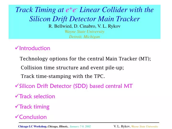
Track Timing at e + e - Linear Collider with the Silicon Drift Detector Main Tracker R. Bellwied, D. Cinabro, V. L. Rykov Wayne State University Detroit, Michigan. Introduction Technology options for the central Main Tracker (MT); Collision time structure and event pile-up;

E N D
Track Timing at e+e- Linear Collider with the Silicon Drift Detector Main TrackerR. Bellwied, D. Cinabro, V. L. RykovWayne State UniversityDetroit, Michigan • Introduction Technology options for the central Main Tracker (MT); Collision time structure and event pile-up; Track time-stamping with the TPC. • Silicon Drift Detector (SDD) based central MT • Track selection • Track timing • Conclusion Chicago LC Workshop, Chicago, Illinois, January 7-9, 2002V. L. Rykov, Wayne State University
Introduction: Options for the technology of Main Tracker Projective • Drift Chamber • Silicon Microstrips 3D pixel • Time projection chamber (TPC): Maximum drift time ~ 40-60 s • Silicon Drift Detectors (SDD): Maximum drift time ~ 6-8 s Event pile-up:How serious is this problem? Chicago LC Workshop, Chicago, Illinois, January 7-9, 2002V. L. Rykov, Wayne State University
Introduction: Collision time-structure and event pile-up time TrainorRf-pulse For NLC/JLC, it is expected ~2.2 hadronic -events per train, in addition to the trigger, with the average number of tracks ~17 and energy deposit in the calorimeter ~100 GeV per such an event. T. Abe et al, Physics Resource Book for Snowmass 2001 and ref. therein Chicago LC Workshop, Chicago, Illinois, January 7-9, 2002V. L. Rykov, Wayne State University
Track time stamping with the TPC • It is recognized that, if the time stampingfor the tracks in the TPCor SDD is not done, it could seriously impact the detector performance, particularly its missing mass resolution. • Sorting out tracks, using the Main Tracker only is always the most desirable option. • The suggested solution for the TPC was to place, at some TPC depth, fast intermediate tracker, made from scintillating fibers and/or silicon intermediate tracking layer inside the TPC. (Physics Resource Book, 2001) Sc. fibers B = 3 T Si layer Chicago LC Workshop, Chicago, Illinois, January 7-9, 2002V. L. Rykov, Wayne State University
Central Main Tracker for SD Design with Silicon Drift Detectors • 5 SDD barrels at radii from 20 to 125 cm. • ~56m2 area covered with ~5600 SDD-wafers of the size 10x10cm2. B = 5 T Chicago LC Workshop, Chicago, Illinois, January 7-9, 2002V. L. Rykov, Wayne State University
STARSilicon Vertex Tracker (SVT) • 3 SDD barrels at radii ~ 6.5, 10.5, and 14.5 cm. • ~0.86m2 area covered with ~216 SDD wafers (double-SDD) of the size 6.3x6.3cm2. • Drift along azimuth (local -axis). Drift along magnetic field (z-axis) is preferable for betterPT-resolution Chicago LC Workshop, Chicago, Illinois, January 7-9, 2002V. L. Rykov, Wayne State University
Tracktime stamping: All SDD drifting along same axis • Correct timing: Hit positions are determined correctly, and fit to a track with a good 2. Chicago LC Workshop, Chicago, Illinois, January 7-9, 2002V. L. Rykov, Wayne State University
Tracktime stamping: All SDD drifting along same axis • Correct timing: Hit positions are determined correctly, and fit to a track with a good 2. • Wrong timing with some hit SDDs drifting in theopposite directions to the others (probability 15/16th=93.75%): Hit positions are determined incorrectly, and do not fit to a track, i.e. 2 is bad. Chicago LC Workshop, Chicago, Illinois, January 7-9, 2002V. L. Rykov, Wayne State University
Tracktime stamping: All SDD drifting along same axis • Correct timing: Hit positions are determined correctly, and fit to a track with a good 2. • Wrong timing with some hit SDDs drifting in theopposite directions to the others (probability 15/16th=93.75%): Hit positions are determined incorrectly, and do not fit to a track, i.e. 2 is bad. • Wrong timing withall hit SDDs drifting thesame direction (probability 1/16th=6.25%): Hit positions are determined incorrectly, but still fit to a shifted track with a good 2. Chicago LC Workshop, Chicago, Illinois, January 7-9, 2002V. L. Rykov, Wayne State University
Model for simulations Vertex Detector (VXD): • 5 CCD layers of the thickness 0.12%X0 each at the distances of 1.2, 2.4, 3.6, 4.8and 6.0 cm • Spatial resolution (both directions), vxd = 5 m • Vertex position assumed to be known at vtx= 2 m Central Main Tracker (MT): • 5 flat SDD layers of the thickness 0.5%X0 each at the distances of 20, 46.25, 72.5, 98.75and125 cm • High voltage = 2500 V/5 cm= 50 V/mm • Drift velocity = 6.75 mm/s • Spatial resolution along anodes, anode = 7 m • Spatial resolution along drift, drift = 10 m Other simulation parameters and characteristics: • Solenoidal magnetic field, B = 5 T • Phase space: -0.8 < cos < 0.8; 0 < < 2 • Multiple scattering in beam pipe, VXD & MT, cryostat, air, etc. was accounted in the both, helical track generation and reconstruction procedures. • More details on the SD-option geometry for the LC detector are at: http://www-mhp.physics.lsa.umich.edu/~keithr/LC/baselines_mar01.html Chicago LC Workshop, Chicago, Illinois, January 7-9, 2002V. L. Rykov, Wayne State University
Track selection:All MT layers drifting along z-axis • Examples of track separation • Various options for drift directions. • t = 10 ns • The best separation is with the drift directions alternated from layer to layer. • In the MT only, no time separation for ~6% of tracks, which hit SDDs, drifting the same direction. Chicago LC Workshop, Chicago, Illinois, January 7-9, 2002V. L. Rykov, Wayne State University
Track selection:Drift in MT layers - zzzz Examples of track separation Chicago LC Workshop, Chicago, Illinois, January 7-9, 2002V. L. Rykov, Wayne State University
Track selection:Drift in MT layers - zzzz Examples of track separation Chicago LC Workshop, Chicago, Illinois, January 7-9, 2002V. L. Rykov, Wayne State University
Various drift axis combinations in MT layers Examples of track separation Randomly Distributed drift directions t = 10 ns The best separation is with the drift axes alternated from layer to layer: zzz and zz Chicago LC Workshop, Chicago, Illinois, January 7-9, 2002V. L. Rykov, Wayne State University
Various drift axis combinations in MT layers Impact on PT-resolution: anode= 7 m drift= 10 m • In the options zzz(the best for time stamping), momentum resolution at high PT deteriorates by ~10%, compared tozzzzz(the best for PT resolution). • There is virtually no worsening of momentum resolution for zzzzdrift. Chicago LC Workshop, Chicago, Illinois, January 7-9, 2002V. L. Rykov, Wayne State University
One more step forward: Track timing Introducing one more parameter: track generation time, in the fits of hit sets, which are tried as potential tracks. Chicago LC Workshop, Chicago, Illinois, January 7-9, 2002V. L. Rykov, Wayne State University
Track timing with various drift axis combinations • With the SDD based main tracker, Track Timing is possible at nanosecond and, at high-PT, even at sub-nanosecond level. • The best drift combinations are zzz (and zz) and … zzzz with no worsening of PT- resolution compared to zzzzz (ultimately the best for PT). Chicago LC Workshop, Chicago, Illinois, January 7-9, 2002V. L. Rykov, Wayne State University
Conclusion • It is shown that, with the SDD based central Main Tracker for the detector at e+e- Linear Collider, the track selection and timing is possible at the nanosecond and even sub-nanosecond level. • This means that, even at the NLC and/or JLC with the bunch spacing at 1.4 ns, each high-PT track can be assigned to a particular bunch crossing at the confidential level of up to ~2. • For the considered here 5-layer central Main Tracker, it is suggested to make layers1, 2, 3 and 5 drifting along z-axis, but layer 4 drifting along the azimuth (-axis) with effectively no negative impact on the tracker’s momentum resolution. In other words, all the above is just for free with the SDD Main Tracker. Chicago LC Workshop, Chicago, Illinois, January 7-9, 2002V. L. Rykov, Wayne State University