Download
1 / 15
210 likes | 661 Views
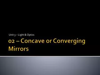
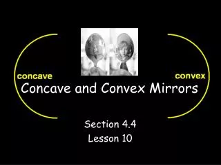
Ray Diagrams in Concave Mirrors. Unit:Optics SNC 2DO. Curved Mirrors. C urved mirrors - have a spherical shape They are called spherical mirrors

E N D
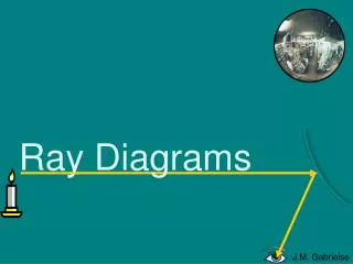
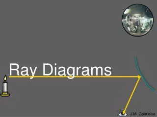
Ray Diagrams in Concave Mirrors Unit:Optics SNC 2DO
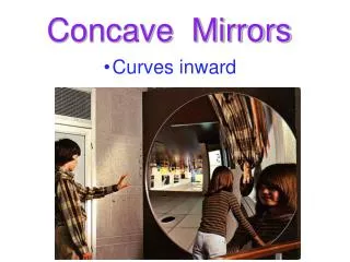
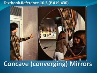
Curved Mirrors • Curved mirrors - have a spherical shape • They are called spherical mirrors • Spherical mirrors can be thought of as a portion of a sphere that was sliced away and then silvered on one of the sides to form a reflecting surface • Concave mirrors were silvered on the inside of the sphere • Convex mirrors were silvered on the outside of the sphere
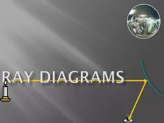
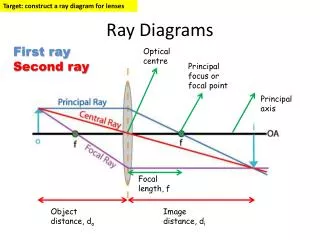
The Elements of the Curved Mirror 1. principal axis 2. center of curvature(C) = the point in the center of the sphere from which the mirror was sliced 3. Vertex (A) = the point on the mirror's surface where the principal axis meets the mirror; it is the geometric centre of the mirror 4. Focal point (F) = midway between the vertex and the center of curvature 5. Radius of curvature (R) = the distance from the vertex to the center of curvature (it is the radius of the sphere from which the mirror was cut) 6. Focal length (f) = the distance from the mirror to the focal point
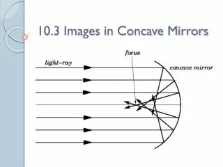
2 Rules for Concave Mirrors: 1. Any incident ray traveling parallel to the principal axis on the way to the mirror will pass through the focal point upon reflection. 2. Any incident raypassing through the focal point on the way to the mirror will travel parallel to the principal axis upon reflection.
Ray Diagrams Step-by-Step 1) 3) 4) 2)
Mirror and Magnification Equations • The mirror equation allows you to calculate the location of the image • In the magnification equation, the magnification, m, tells you the size, or height, of the imagerelative to the object using object and image distances. Mirror Equation: 1/f =1/di+1/do Magnification Equation: m = hi/ho= -di/do The image height, hi, is negative if the image is inverted relative to the object.
Problems: Mirror Equationsand Concave Surfaces • Copy the sample problem on page 426 • Do Practise Problems 1-5 on page 427
Problem: • The diagram below shows two light rays emanating from the top of the object and incident towards the mirror. Describe how the reflected rays for these light rays can be drawn without actually using a protractor and the law of reflection.
Answer: • These two incident rays will pass through the image point for the top of the object. In fact, any light rays emanating from the top of the object will pass through the image point. Thus, merely construct a ray diagram to determine the image location; use the two rules of reflection. Then draw the reflected rays for the two given incident rays through the same image point.
Homework: Read and make notes on pages 419-430 and answer Review Questions 1-8 on page 430.