Download
1 / 24
240 likes | 424 Views
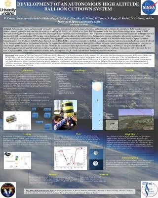
Free Fall Stability Analysis of High Altitude Balloon Reentry Vehicle Using CFD. J Snyder, C. Barnes, Jessica Rinderle , Oleg Shiryayev a nd Joseph Slater. Objectives. Release free fall capsule at 90,000 feet Deploy parachute at 65,000 ft Develop launch/flight simulation

E N D
Free Fall Stability Analysisof High Altitude BalloonReentry Vehicle Using CFD J Snyder, C. Barnes, Jessica Rinderle, Oleg Shiryayev and Joseph Slater
Objectives • Release free fall capsule at 90,000 feet • Deploy parachute at 65,000 ft • Develop launch/flight simulation • CFD modeling of free-fall • Validate CFD model • Reduced order nonlinear rigid body dynamic model identified CFD from • Compare to experimentally identified dynamic model
Background • 5thyear of High Altitude Balloon program • “Our laboratory is at 100,000 feet” • Cost-effective near space experimentation • 100% recovery rate (15 flights) • Prior experiments • Reliable balloon tracking systems • Deployment of shape memory composite tube • Three dimensional deployable truss using shapememory composites
HiBAL flight regulations • FAA FAR 101 Subpart D • No flight permission required underexempt rules (must notify of launch and land) • 12 lb total payloadlimit • 6 lbs per package • 50 lb impulse max load capability… units? • Stay out of controlled areas • Many shades of gray in rules
Experimental Setup • Styrofoam capsule • Control • DTMF • Cut-down initiation • Parachute deployment • Tracking • GPS/APRS via Micro-Track, Tiny Track • Parachute
Data Acquisition System • VectorNav VN-100T sensor board • Temperature calibrated to 40o C • Accelerations • Angular rates • Magnetic sensors • Output to SparkFunLogomaticV2 Serial Data Logger • Quaternion (via EKF) • Acceleration X, Y, Z • Angular rates (via EKF)
Test Flight • Ran a flight to test the ability of the data acquisition system • Also tested cut down system • Need to reliably cut down the reentry vehicle from the balloon to obtain correct free fall data • Test flight consists of the data acquisition system enclosed in a Styrofoam cooler • Numerous parachute deployment tests
Data Processing • Pre-processing • Removal of corrupted lines • Removal of bias • Smoothing • Stability Analysis • Visualization of spatial orientation of the capsule • Estimation of aerodynamic forces and moments • Correlation with CFD data
CFD Analysis • The 3 Dimensional reentry vehicle is forced to oscillate rotationally about the z axis. • Analysis provides moments and forces as a function of rotation and angular velocity that will be used to identify the rigid body dynamic equations
Simulations Methods • All simulations were run with air at 60,000 ft • Two cases of simulations were run • High amplitude oscillating motion with selected descent velocities • A = 900 ω = .5 rad/s • 3 m/s, 14 m/s, 28 m/s, 42 m/s, 55.8 m/s • Reynolds number from 15,690 – 291,836 • Low amplitude oscillationmotion with over a set (grid) of angular frequencies and descent velocities • A = 5oω = 3 rad/s, 6 rad/s, 9 rad/s, 12 rad/s, and 15 rad/s • 3 m/s, 14 m/s, 28 m/s, 42 m/s, 55.8 m/s Density, ρ(kg/m2) 0.122 Viscosity, µ (kg/m*s) 1.422 × 10⁻⁵
y CFD Model x z • 3D teardrop is surrounded by a cylinder, which is in a larger rectangular domain • The cylinder allows for rotational motion as needed outlet teardrop inlet
Discontinuous Mesh • SC/Tetra has a discontinuous mesh setting, which allows flow field states to transfer between two separately created meshes that have adjacent faces. • The two model portions are meshed separately with an unstructured grid, and then combined to form the final mesh model. • For the simulations two final meshes have created so far, a coarse grid and a finer grid.
Coarse Mesh • The course mesh has approximately 41,000 elements • To the right is a zoomed in view of the mesh near the teardrop
Refined Mesh • The refined mesh was created to verify mesh independence of the solution • The refined mesh has 1,199,314 elements
y Simulation ResultsOscillation motions with varying velocity x z
y x z
y x z
y x z
Conclusion • CFD simulations are continuing • Test flight was partially successful in required cut down methods • Ready to obtain flight data from reentry vehicle
Acknowledgements • Industry advisors: Bruce Rahn, Steve Overmeyer, Steve Mascarella • Other faculty advisors: George Huang, John Wu • Brent Guenther,BesmiraSharra and other team members • Ohio Space Grant Consortium • NSF CCLI Award 0837677 • Wright State University Physics Department and Cornerstone Research Group (equipment) • Wright State University (curriculum innovation funding)