Download
1 / 8
80 likes | 83 Views
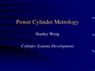
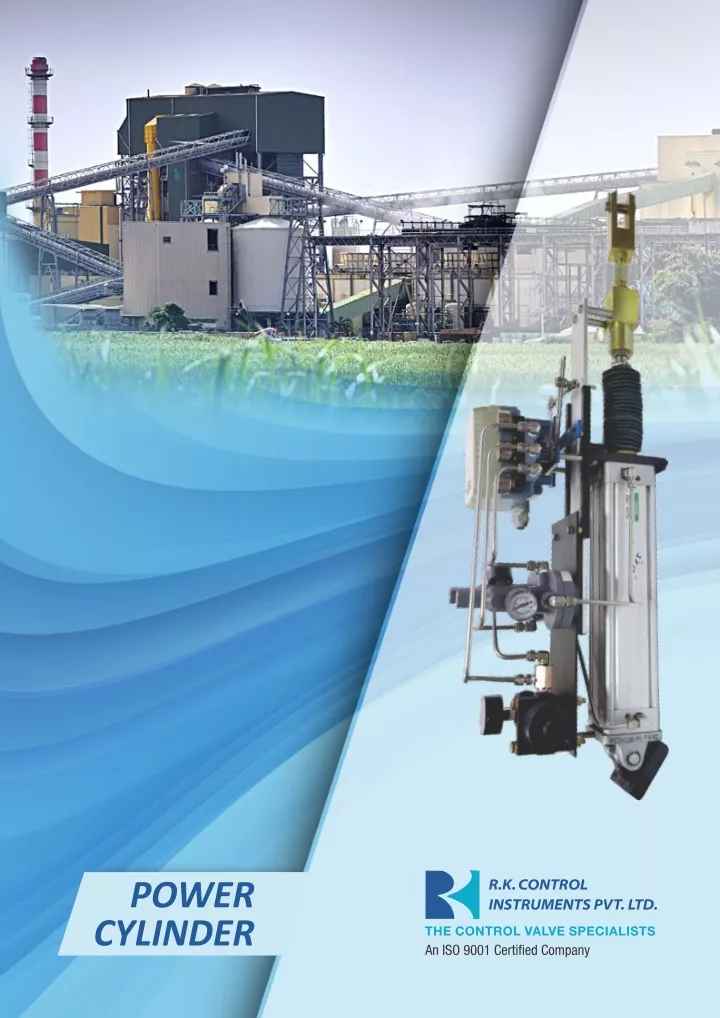
RK Power Cylinder consists basically of a Double Acting Cylinder, Positioner, Air Filter Regulator.<br><br>This Power Cylinder has been designed to operate as an actuator in a pneumatic control system, to position the final control element in accordance with the controller signal. https://rkcipl.co.in

E N D
SPECIFICATIONS Maximum working pressure : 10 kg/cm (150 psi) clean dry air Maximum working temperature : 80 degree C ( 176 degree F) Control signal pressure range Accuracy : : Within 2.5% of full stroke. 0.2 to 1 Kg/cm Air Consump?on : 1 scfm at supply pressure of 4 kg/cm at steady state Characteris?cs : Linear with standard cam Piston movement : Direc?on of piston movement in rela?on to signal can be reversed by the reversing the cam and re-rou?ng the piping Material : Cylinder Anodized Aluminium upto 6 “ bore MS Seamless steel tube hard chrome plated for 8 “ bore and above Piston Rod : Hard chrome plated steel Seals : NBR as Standard / Viton for high temperature applica?on up to 180 degree cen?grade ( 356? F) Bore Sizes : 3”, 4”, 6”, 8”, 10”, 12” Strokes : 6”, 8”, 12”, 16” Engineered specials available on request Accessories : Pneuma?c/ Electropneuma?c / Digital Posi?oner (HART/FF), Limit switches, Volume booster, Air Lock Relay can be provided on request and based on applica?ons. POWER CYLINDER DE-CODIFICATION SHEET 1, 2 3, 4 5, 6 7 8 9 10 11 12 13 14 Power Cylinder PC 3” 03 4” 04 Base Plate with Pin (Hinge Bracket) Bellows Handwheel No 0 No 0 Storke Leather Series Bore Dia Length Cylinder Material Aluminium Seals Service On-Off TYPE Moun?ng Rare Plate A NBR N O No 0 Regular R P 4” 04 6” 06 Chrome Plated Steel Tube C Viton V Regula?ng R Yes 1 Yes 1 Yes 1 Special S Rare Trunnion T 5” 05 8” 08 Special Mount S 6” 06 10” 10 8” 08 12” 12 10” 10 14” 14 12” 12 16” 16 18” 18 20” 20 1
Fig. 01 LAYOUT OF POWER CYLINDER AND POSITIONER 1 3 4 5 6 2 18 7 8 9 10 11 12 13 14 15 16 17 19 Range adjustment Screw Pilot Valve Body Output ‘A’ 1 6 11 16 Folower Arm Pilot Valve Spool Output ‘B’ Output Port ‘B’ 2 7 12 17 Take-off Arm Pneuma?c Power Cylinder Zero Adjustment Lock Knob Feedback Spring Output Port ‘A’ 3 8 13 18 Double Diaphragm Sensor Assly Turn Buckle With Fork Zero Adjustment Signal 3-15 psi 4 9 14 19 Range adjustment Lock Screw Supply 5 10 15 Balance Beam Fig. 02 MOUNTING OPTIONS REAR PLATE MOUNTING REAR TRUNNION MOUNTING 3