Download
1 / 33
330 likes | 334 Views
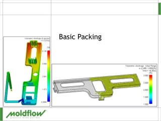
Learn how to produce optimized packing profiles to reduce warpage in molded parts and improve manufacturing efficiency. Discover the importance of volumetric shrinkage variation and how to create constant packing profiles. Explore the key factors determining acceptable shrinkage and pressure, and how to optimize fill, cool, and decay profiles. Enhance part flow and optimize cooling for better results.

E N D
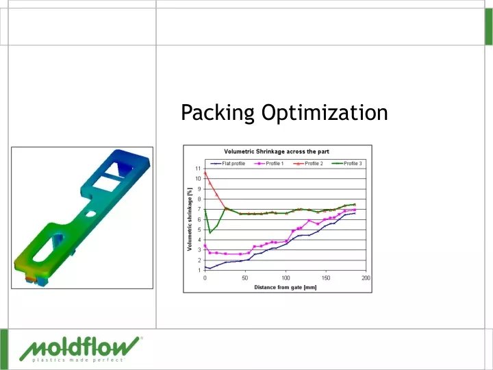
Introduction • Aim • Learn how to produce optimized packing profiles • Why do it • Volumetric shrinkage variation is a major cause of warpage • Overview • Optimize fill & cool • Create constant packing profile • Use to develop decayed profile • Reduce pressure over time to create uniform shrinkage
Volumetric Shrinkage • Part’s size and material type determines acceptable range of volumetric shrinkage • Larger parts will have a larger acceptable magnitude and range • Volumetric shrinkage • Magnitude • Relates to linear dimensions of the part • Range • Relates to the warpage of the part • Target • Low and uniform shrinkage
Packing Pressure Filling Time Definitions • Packing pressure • Magnitude of pressure applied after the velocity to pressure switch-over (V/P switch-over) • Packing time • The time pressure is applied after V/P switch-over
Moldflow Packing Packing Pressure Filling Time Definitions • Hold pressure • Used interchangeably with packing time • Also used to define a pressure other than “packing” • Normally a lower value • Hold time • The time hold pressure is applied • In process settings wizard • No difference between packing and holding Machine Holding
Definitions • Cooling time • The time the part is held in the mold after pressure is removed • Also called cure time • Specified with a packing analysis if cooling analysis is not done first
Pack Profile • Constant pressure • Has 1 or 2 steps at a constant pressure • Two steps is similar to profiled packing • Used when machines are not capable of profiled packing • May be as good as profiled packing if the part has a wide variation in thickness • Pressure profile • A continuous change in pressure over time Constant Pressure Time Decay Time
Pack/Hold Control • %Filling pressure vs time • Default – use when • Not sure what the fill pressure will be • Clamp tonnage not an issue • Packing pressure vs time • Used when the packing pressure is known • Hydraulic pressure vs time • Intensification ratio * hydraulic pressure = pack pressure • Not often used • %Maximum machine pressure vs time • Rarely used only used if molding machine uses this method and need to duplicate a process
Packing Analysis Setup • Packing Profile • Packing Pressure • Packing Time • Cooling Time
Using Pack Profiles • Profiles make volumetric shrinkage more uniform • Volumetric shrinkage is determined by the pressure on plastic when it freezes • More pressure less shrinkage • Parts always have pressure gradient across them • Profiles reduce packing pressure over time • Reduces pressure closer to gate • Increases volumetric shrinkage near the gate • Makes it closer to the shrinkage at the end of fill • Reduces “over-packing”
Pressure Time Using Pack Profiles • Use decayed profiles when • The machine is capable • The wall thickness variation is not great • Thicker walls require higher pressures to achieve the same magnitude of volumetric shrinkage as a thinner wall • The warpage is critical
Optimize Flow Optimize Fill Balance/Size Runners Cooling analysis? Y Optimize Cooling N Optimize Packing Profile End Optimizing Part Flow • Optimize the filling of the part • Prepare model • Select material • Determine gate location • Optimize processing conditions • Resolve filling problems • Size/balance runners • Size gate • Size/balance runners • Optimize the cooling of the part
Optimize Packing Profile Determine Initial pack pressure Max so 80% of machine clamp needed Determine initial pack timeGate must freeze Base on previous Fill or Cooling analysis Run first packing analysis Review first packing analysis results Volumetric Shrinkage, Pressure XY plot, Frozen Layer Fraction in gate area Create initial packing profilePressure decays during packing to make shrinkage more uniform Run second packing analysis Review results with initial packing profileVolumetric shrinkage, Pressure XY plot, Frozen layer fraction in gate area Run Packing Analysis Revise Packing Profile Volumetric Shrinkage Acceptable? N Y End Optimizing a Packing Profile • Determine pack pressure • Consider clamp force • Determine pack time • Gate must freeze • Run initial analysis • Review results • Define first profile • Run • Review and iterate
Determine Initial Pack Pressure • Default pack pressure 80% of fill pressure • Typical pack pressure range 20% to 100% of fill pressure • Ensure clamp force not exceeded • Use 80% of clamp machine limit to determine maximum pack pressure • Use any pack pressure that does not exceed clamp force Unit conversion =100 metric, 2000 English units
Determine Initial Pack Time • Use long pack time to ensure gates have frozen • Estimate pack time from • Cooling analysis • Injection+Packing+Cooling minus V/P switchover from fill analysis • Fill analysis • Freeze time result • If gate not frozen during pack time of first packing analysis • Increase pack time and re-run
Run and Review the First Packing Analysis • Ask • Is volumetric shrinkage too high or low • If shrinkage at end of fill too high – the packing pressure must be increased • Is volumetric shrinkage distribution too large • If yes continue with packing optimization • Has the gate frozen • Review • Volumetric Shrinkage at Ejection • Volumetric Shrinkage path plot • Pressure XY plot • Hold pressure • Frozen Layer fraction
Volumetric Shrinkage • At ejection • Should be 2% variation or less • Nominal wall of part • Path plot • Shows shrinkage at various locations on part • Animated through time
Plot XY Graph of Pressure • Node 2351 at top of sprue • Represents input profile • Node 304 at End of fill • Other nodes between gate and EOF • Curves should be nearlyon top of each other
Hold Pressure • Maximum pressure after V/P switchover • Should be uniform • Never will be completely
Frozen Layer Fraction • Determine when gate freezes • Value of 1.0 – cross section is frozen • Turn of nodal averaging • Animate through time • Example, • Case A has double the pack pressure as B A B
Constant Pressure time Pres. Transition point Decay Time Pressure at zero Time Create Initial Packing Profile • Time for start of decay can be determined from pressure trace at the end of fill • Time for end of decay can be determined from gate freeze time
Calculate Constant Pressure Time • Query pressure curve at end of fill • At maximum pressure • When pressure goes to zero • Find the time midway between these times • Defines transition point • Subtract V/P switchover from Transition point • Round to 0.1 seconds (1.75+ 5.75) / 2 = 3.75 3.75 – 0.81 = 2.5
Calculate Decay Time • Plot Frozen layer fraction • Turn off nodal averaging • Animate the plot manually • Note the time the gate area freezes • 10.25 seconds almost all frozen • 11.75 completely frozen • Subtract transition point • Round to 0.1 sec. 11.75 - 3.75 = 8.0
Determine Packing Pressure • Original packing analysis done by Percentage of fill pressure • Review Screen output to determine the pack pressure used in the first analysis • Round up to the next • 1 MPa • 100 psi Packing phase: |-------------------------------------------------------------| | Time |Packing| Pressure | Clamp force| Status | | (s) | (%) | (MPa) | (tonne) | | |-------------------------------------------------------------| | 0.84 | 0.00 | 22.70 | 8.48 | P | | 1.05 | 1.02 | 22.70 | 15.91 | P | | 1.75 | 4.51 | 22.70 | 16.29 | P | | 2.25 | 6.99 | 22.70 | 15.99 | P |
Write the Profile Run a packing analysis with this revised profile
Review Results with Initial Packing Profile • Volumetric shrinkage • Shrinkage a little more uniform • Shrinkage primarily increased near the gate • Shrinkage must be made much more uniform
Review Results with Initial Packing Profile • Pressure • Flat profile forces pressures to be closer but not enough Flat Profile Profile 1
Continue to Improve the Profile • Decay pressure faster • Forces curves closer together • Don’t decay to zero • Based on end of fill (EOF) node • Determine when EOF node reaches 5 MPa • About 5.0 seconds • Transition point = 3.75 • Decay to 5 MPa = 1.3 Sec 5.0 - 3.75 = 1.3
Continue to Improve the Profile • Frozen layer fraction • Determine gate seal time • Subtract Time of EOF node to reach 5 MPa from gate seal time • Create revised profile • Run analysis with revisedprofile 11. 5 – 5.0 = 6.5
Review Results • Compare volumetric shrinkage • Shrinkage more uniform except around gate • Pressure curves closer together • Adjust profiles as necessary A B A= Flat profile, Low Pressure B= Profile 4
Fine Tuning the Packing Profile • To adjust the end region: • Adjust constant-pressure time • Shorten, to increase volumetric shrinkage • Lengthen, to decrease volumetric shrinkage • To adjust the gate region: • Change rate of pressure decay • Faster, to increase volumetric shrinkage • Slower, to decrease volumetric shrinkage • To adjust the mid region: • “Step” decay • Faster initial decay, to increase volumetric shrinkage • Slower initial, to decrease volumetric shrinkage
Exercise • One cavity model of the Snap Cover • Occurrence numbers used to represent the 2-cavity tool • Optimize packing profile to minimize volumetric shrinkage