Download
1 / 15
150 likes | 301 Views
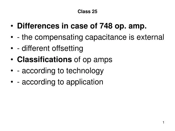
Class 25. Differences in case of 748 op. amp. - the compensating capacitance is external - different offsetting Classifications of op amps - according to technology - according to application. power stage compl. E-follower; current limiting small R out. main amp. big A v (CE)

E N D
Class 25 • Differences in case of 748 op. amp. • - the compensating capacitance is external • - different offsetting • Classifications of op amps • - according to technology • - according to application
power stage compl. E-follower; current limiting small Rout main amp. big Av (CE) frequency-compensation input diff amp. big CMRR offset setting phase addition big Rind, Rinc and Rvd1 Class 25 • General structure
v1 Avd v1 Class 25 • CHAPTER 8: MODELS OF OP-AMPS • Ideal model • Avd = ∞ • v1 = 0 • CMRR = ∞ • Rind , Rinc = ∞ ohm • Rout = 0 ohm
vic / CMRRr vic CMRRi= vo vic Class 25 • CMRR model • Verifying by calculation of vo
2Rinc Rout v1 ~Rind 2Rinc Avd (s)v1 Class 25 • Impedance model • The Avd gain is like the gain of a one-pole amplifier
ii voff ii ideal amp. real amp. vi vo vo vi ioff Class 25 • Offset model • notion of offset (asymmetric amplifier)
voff Rg ii ideal amp. vgoff vi vo = 0 ioff Class 25 • Offset compensation • The resulting offset voltage • vgoff = ioffRg + voff
voff Ib+ Ib- the voltage generators of the two sides can be unified; Ib+ and Ib- are the input bias currents Class 25 • The offset model of op-amps • Step 1
voff Ib ioff/2 Ib Here the bias currents are substituted by common (Ib) and differential components (ioff; this is the offset current): Ib = (Ib++Ib-)/2 ioff = Ib+-Ib- Class 25 • Step 2
voff ioff/2 If the internal resistances of the embedding circuit seen by the + and - input points are equal, the two Ib generators can be left out Class 25 • Step 3
Class 25 • Noise model • Typical noise sources • The notion of the power spectral density • Voltage and current spectral densities • Dimensions • The addition of such quantities is carried out by the so-called vector addition
vn in in Class 25 • The idea of modeling is similar to that in case of the offset
sn log-log scales -20 dB/D snw f fcr Class 25 • The spectral density diagram and its mathematical expression
vi vo R2 R1 Class 25 • CHAPTER 9: BASIC CONNECTION ARRANGEMENTS OF OP-AMPS • Non-inverting basic amplifier • Properties
R2 R1 i2 vi i1 vo parallel voltage feedback Class 25 • Inverting basic amplifier • Properties