Download
1 / 30
300 likes | 305 Views
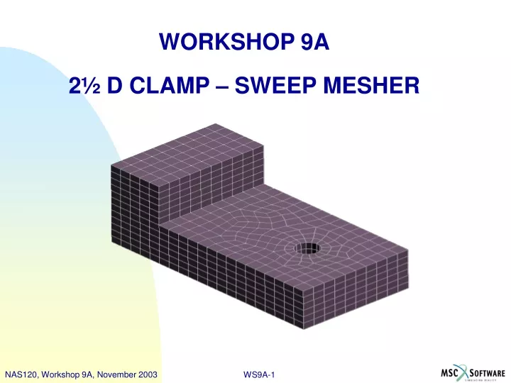
WORKSHOP 9A 2½ D CLAMP – SWEEP MESHER. NAS120, Workshop 9A, November 2003. WS9A- 1. Problem Description Analyze the clamp shown below:. R = 10 mm. 50 mm. 30 mm. 60 mm. 30 mm. 150 mm. 100 mm. 200 mm. Problem Description (cont.)

E N D
WORKSHOP 9A 2½ D CLAMP – SWEEP MESHER NAS120, Workshop 9A, November 2003 WS9A-1
Problem Description • Analyze the clamp shown below: R = 10 mm 50 mm 30 mm 60 mm 30 mm 150 mm 100 mm 200 mm
Problem Description (cont.) • A pressure loading of 1 N/mm2 is applied to the top face. • Constrain the bolt hole in all three translations. • Material Properties: • E = 109 x 103 N/mm2 • n =0.3
Workshop Objectives • Practice the construction of a 2 ½ D solid model by sweeping 2D elements.
Suggested Exercise Steps • Create a new database. • Create surface geometry. • Mesh the surface to create CQUAD4 plate elements. • Sweep the plate elements into solid elements. • Create a boundary condition. • Create a pressure load. • Define material properties. • Create Physical Properties. • Run the finite element analysis using MSC.Nastran. • Plot displacements and stresses.
Step 1. Create New Database a a • Create a new database called clamp.db • File / New. • Enter clamp as the file name. • Click OK. • Choose Tolerance Based on Model. • Enter 200 for the Approximate Maximum Model Dimension. • Select MSC.Nastran as the Analysis Code. • Select Structural as the Analysis Type. • Click OK. d e f g b c h
Step 2. Create Surface Geometry • Create the first surface • Geometry: Create / Surface / XYZ. • Enter <150 100 0> for the Vector Coordinate List. • Click Apply. a b c
Step 2. Create Surface Geometry Add a hole to the surface • Geometry: Edit / Surface / Add Hole. • Enter 10 for the Hole Radius. • Click in the Surface box. • Screen Pick Surface 1. • Enter [50 50 0] for the Center Point List. • Click Apply. a b c e d f
Step 2. Create Geometry Create another surface • Geometry: Create / Surface / XYZ. • Enter <50 100 0> for the Vector Coordinate List. • Click in the Origin Coordinates List box. • Screen Pick the origin as shown. a b c d
Step 3. Create Mesh Create a surface mesh • Elements: Create / Mesh / Surface. • Set the Mesher to Paver. • Click on Paver Parameters. • Set the Max h/L value to 0.05. • Click OK. • Click in the Surface List box. • Rectangular pick both surfaces. • Set the Global Edge Length to 10. • Click Apply. a b g c d f h e i
Step 3. Create Mesh a View the meshed surface • Click on the Iso 3 View Icon.
Step 4. Create Solid Elements Sweep the plate elements into solid elements. • Elements: Sweep / Element / Extrude. • Click Mesh Control. • Set the Number of Elements to 6. • Click OK. • Set the Direction Vector to <0 0 1>. • Set the Extrude Distance to 30. • Click in the Base Entity List box. • Polygon pick the 2D elements as shown. • Click Apply. a c b h d e f g i
Step 4. Create Solid Elements Sweep the plate elements into solid elements. • Elements: Sweep / Element / Extrude. • Click Mesh Control. • Set the number of elements to 12. • Click OK. • Set the Direction Vector to <0 0 1>. • Set the Extrude Distance to 60. • Click in the Base Entity List box. • Polygon pick the rest of the 2D elements as shown. • Click Apply. a c b h d e f g i
Step 4. Create Solid Elements Delete the plate elements • Elements: Delete / Element. • Pick the Quad Element Filter. • Rectangular pick all elements. • Click Apply. a b d c
Step 4. Create Solid Elements Verify element boundaries • Elements: Verify / Element / Boundaries. • Click Apply. a b
Step 4. Create Solid Elements Equivalence the model • Elements: Equivalence / All / Tolerance Cube. • Click Apply. a b
Step 4. Create Solid Elements Verify element boundaries again • Elements: Verify / Element / Boundaries. • Click Apply. a a b
Step 5. Create Boundary Condition a Set Picking Preferences • Select Preferences / Picking • Choose Enclose Centroid for Rectangle/Polygon Picking. • Click Close. b c
Step 5. Create Boundary Condition Create the boundary condition • Loads/BCs: Create / Displacement / Nodal. • Enter bolt_hole as the New Set Name. • Click Input Data. • Enter <0 0 0> for Translations • Click OK. a d b c e
Step 5. Create Boundary Condition c d Apply the boundary condition • Click Select Application Region. • For the Geometry Filter select FEM. • Click on Front View Icon. • Zoom in using View Corners. • Polygon pick nodes on the bolt hole. • Click Add. • Click OK. • Click Apply. b f c a g h
Step 6. Create Load Create the pressure load • Loads/BCs: Create / Pressure / Element Uniform. • Enter clamp_pressure as the New Set Name. • Click Input Data. • Enter 1 for the Pressure. • Click OK. a d b c e
Step 6. Create Load c d Apply the pressure load • Click Select Application Region. • For the Geometry Filter select FEM. • Click on Bottom View Icon. • Click on Fit View Icon. • Rectangular pick the top surface of solid elements as shown. • Click Add. • Click OK. • Click Apply. b e f g a h
Step 7. Define Material Properties Create an isotropic material • Materials: Create / Isotropic / Manual Input. • Enter titanium as the Material Name. • Click Input Properties. • Enter 109e3 for the elastic modulus and 0.3 for the Poisson Ratio. • Click OK. • Click Apply. a d b c f e
Step 8. Create Physical Properties Create element properties • Properties: Create / 3D / Solid. • Enter solid as the Property Set Name. • Click Input Properties. • Click on the Select Material Icon. • Select titanium as the material. • Click OK. a d b c e f
Step 8. Create Physical Properties Apply the element properties • Click in the Select Members box. • Select the Solid Element filter. • Rectangular pick all elements as shown. • Click Add. • Click Apply. b c a d e
Step 9. Run Linear Static Analysis Choose the analysis type • Analysis: Analyze / Entire Model / Full Run. • Click Solution Type. • Choose Linear Static. • Click OK. • Click Apply. a c b d e
Step 10. Plot Displacements and Stresses Attach the results file • Analysis: Access Results / Attach XDB / Result Entities. • Click Select Results File. • Choose the results file clamp.xdb. • Click OK. • Click Apply. a c d b e
Step 10. Plot Displacements and Stresses Create a deformation plot for the mid span result case • Results: Create / Quick Plot. • Select Stress Tensor as the Fringe Result. • Select Von Mises as the Fringe Result Quantity. • Select Displacements, Translational as the Deformation Result. • Click Apply. a b c d e