Download
1 / 27
270 likes | 470 Views
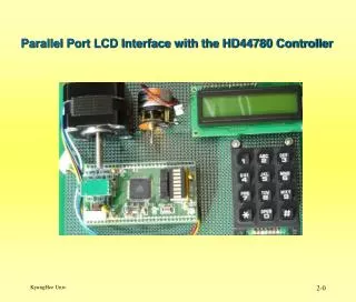
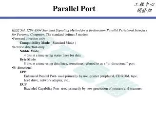
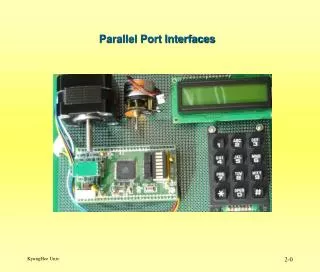
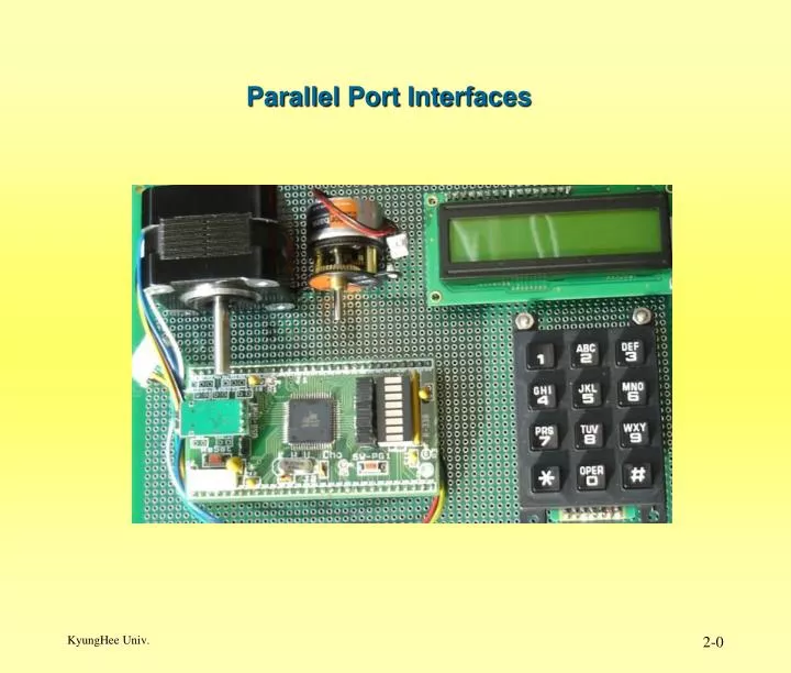
Parallel Port Interfaces. Interfacing a Switch to the Computer. ATmega128 은 내부에 Internal Pull-up 저항을 갖고 있다. Parallel Input/Output Port 초기화 예. #include <avr/io.h> void port_init(void) { PORTA = 0x00; // Input Port Pull-up(DDRA=0, PORTA=0,PUD=0) DDRA = 0x00; // Input Port

E N D
Interfacing a Switch to the Computer • ATmega128은내부에 Internal Pull-up 저항을 갖고 있다.
Parallel Input/Output Port 초기화 예 #include <avr/io.h> void port_init(void) { PORTA = 0x00; // Input Port Pull-up(DDRA=0, PORTA=0,PUD=0) DDRA = 0x00; // Input Port PORTF = 0x00; DDRF = 0xff; // Output Port } unsigned char data; int main(void){ port_init (); while(1){ data = PINA; PORTF = data; } }
Hardware Debouncing • 스위치 On-Off 시, 스위치의 기계적인 특성과 회로내의 L 과 C의 영향으로 원하지 않는 펄스가 발생한다.
Bouncing 문제에 의한 SW 오 동작 • 아래 그림과 같이 실제 I/O Port 에 스위치를 연결하는 경우 bounce 가 발생하여 오 동작의 원인이 된다.
Capacitor를 사용한 Hardware Debouncing • Switch의 Bounce 문제를 해결하기 위하여 Capacitor 를 SW 와 병렬로 연결하면 R-C회로가 Low pass filter 로 작동하여 1차로 Bounce를 줄이는 효과가 있다. • 그러나 R-C 적분기 만으로는 Bounce 문제를 완전히 해결하지 못하기 때문에 Schmitt-Trigger Inverter( 74HC14 )를 사용하여 Bounce를 제거한다.
Capacitor를 사용한 Hardware Debouncing • Switch 가 On 될 때 Capacitor 와 • Schmitt-Trigger Inverter( 74HC14 )의 효과.
Capacitor를 사용한 Hardware Debouncing • Switch 가 Off 될 때 Capacitor 와 • Schmitt-Trigger Inverter( 74HC14 )의 효과.
Capacitor를 사용한 Hardware Debouncing • Capacitor 값을 결정하는 방법
Capacitor를 사용한 Hardware Debouncing • SW가 닫치는 순간 이론적으로는 SW를 통하여 c에충전된 전하가 순간적으로 방전되어야 한다. • SW를 통하여 순간적으로 큰 전류가 흐르는 경우 아래 그림과 같은 Spark 가 발생한다.
Capacitor를 사용한 Hardware Debouncing • SW를 통하여 순간적으로 과도한 전류가 흐르는 것 을 막기 위하여 SW와 직렬로 적당한 저항을 접속한다. • 이 저항(22Ω)은 아래 예에서 10K보다는 대단히 작고 SW 저항(약0.1Ω) 보다는 대단히 커야 한다.
Capacitor를 사용한 Hardware Debouncing • Schmitt trigger 회로는 Multiple transition 을 막기 위하여 사용한다. • 74HC04 와 74HC14의 전달 특성의 차이 • 74HC14는 Hysteresis 특성을 갖는다. 0
Hysteresis 특성을 갖는 74HC14 과 보통 Gate(74HC04) 의 비교 • 왜 보통 Gate(74HC04) 가 사용되어서는 안되고 • Hysteresis 특성을 갖는 74HC14이 사용되어야 하는가를 보여 주는 그림
Software Debouncing • uP의 실행 속도에 충분한 여유가 있는 경우, • Bouncing을 Software 적으로 제거하는 것이 가능하다.
Software Debouncing • SW 위치 변동이 발생한 후 Bouncing 시간 만큼 Wait Time 을 갖는다.
Software Debouncing의 예 *Old에 현재 SW의 상태를 저장하고 10mS동안 이 값이 변동하지 않는 경우 SW 값으로 결정하고, *만약 10mS 이내에 SW 값이 변동하면 Old에 새 SW 값을 저장하고 다시 10mS 동안 SW 값이 변동하지 않을 때 까지 반복한다.
Switch debouncing using interrupts in C software. cho_key_debounce_timer3 참고요
Basic Approaches to Interfacing Multiple Keys • Key Interface 방식에 따라 아래와 같은 수의 SW 사용 가능 • Direct interface : Input Port 수 • Scanned interface : Output Port 수 * Input Port 수 • Multiplexed interface : (Output Port 수 **2) * Input Port 수
Basic Approaches to Interfacing Multiple Keys • Scanned Interface 방식을 위한 Scanning Patterns 예 • Open Collector Output 사용 • Output은 HiZ 또는 Low 상태를 갖는다. Scanning Patterns for a 4 by 4 matrix keyboard
Basic Approaches to Interfacing Multiple Keys Scanning Patterns for a multiplexed 16 by 16 matrix keyboard
4 by 4 Scanned Keyboard • PC7-PC4 를 Open Collector Output으로 사용 한다. • STRA단자를 이용한 Interrupt를 사용 한다.
4 by 3 Scanned Keyboard • Scanning은 아래와 같이 2단계로 이루어 진다. • PV4 – PC7 중 하나의 Output만 0을 출력하도록 한다. • Input Port를 읽는다.( 0 : Pressed , 1: Not Pressed ), 또는 PE4 – PE6 의 외부 Interrupt 기능을 이용 한다.
8.1.6 4 by 4 Scanned Keyboard Patterns for a 4 by 4 matrix keyboard
4 by 4 Scanned Keyboard 프로그램 예 cho_keypad_basic 프로그램 참고 요
Multiplexed/Demultiplexed Scanned Keyboard • 16 Row, 9 Columns interface로 144 Key를 사용 할 수 있다. • 4 to 16 Demultiplexer(74159) 와 10 to4 line Priority Encoder (74147)를 사용 • 74147의 출력은 Column No(위치)의 Negative Logic 이 된다. • 74147 의 모든 입력이 High인 경우 출력은 1111 이 된다. • Interrupt를 이용한 주기적인 Polling 을 사용 한다. I/O Port