Download
1 / 28
280 likes | 372 Views
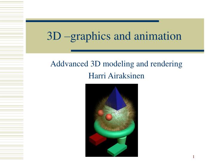
3D –graphics and animation. Addvanced 3D modeling and rendering Harri Airaksinen. Using set of 2D pictures to create 3D models or edit them. Logical Operators. Union , is also known as and Intersection , is called or Difference , is called not. Surface trim.

E N D
3D –graphics and animation Addvanced 3D modeling and rendering Harri Airaksinen
Logical Operators • Union, is also known as and • Intersection, is called or • Difference, is called not
Fitting ja Blending • Fitting = get rid of small gaps between surfaces • Blending = way of merging two surfaces
Noise and Wave modifiers • Ready made functions to control objects behavior UI: Modifiers Parametric Deformers see the list
Colors • red, blue, and yellow (RBY) • Cyan, Magenta, Yellow, and Black (CMYK) • Red, Green, and Blue (RGB) Pure green = 0-255 -0 Greenish light blue = 150-200-255 Yellowish dark orange = 120-80-30
Colors • Hue, Lightness, Saturation HLS
Rendering • 3D Studio Max; Rendering Render
What can be seen and what can’t be seen hidden surfaces - different algoritms - • Area subdivision (1969), Watkins' scan line (1970), and Newell's depth sort (1972) • Z-Buffer: all objects in the scene are sorted by their Z position, or depth, in the scene. This depth information is kept in a buffer, and made available to the rendering process as the hidden surface removal calculations are performed
Ray Tracing- follow the light method • It would be impractical to trace all the rays of light emitted by a light source in a scene because MANY of them NEVER REACH THE CAMERA so: ray tracing programs trace the rays of lights backwards, from the camera to the light source -> This minimizes the amount of wasted calculations
Ray Tracing- 3D Studio Max • Most ray tracing programs use different controls: • The reflection ray • The transparency or refraction rays • The shadow rays.
Ray Tracing; in action • Reflection rays travel through the scene in a straight way, and they bounce off the reflective surfaces they hit at the same angle at which they hit them: • Once a point in three-dimensional space has been hit by a ray and the value of that surface has been calculated • Next a shadow ray is shot from that point to the center of each light source in the scene. That point in three-dimensional space will only be visible if the shadow ray does not encounter another object before reaching the light source
Ray Tracing; in action • If the ray tracing process encounters transparent surfaces in the scene then refraction rays are generated, to calculate the amount of light refraction • Tracing depth how many reflections will be calculated? The light is loose some part of energy in every reflection
Radiosity - calculate diffuse interreflection between surfaces • Illumination engineering theory and also on the principles of energy transfer • Environment into areas or clusters of polygons according to the way in which light affects them. Polygons in a radiosity calculation are typically catalogued: • Light sources • Light-receiving surfaces • Light-blocking surfaces
Radiosity - calculate diffuse interreflection between surfaces
Radiosity - calculate diffuse interreflection between surfaces
Radiosity - calculate diffuse interreflection between surfaces
Radiosity - calculate diffuse interreflection between surfaces • Radiosity calculation typically require large amounts of main memory (RAM), and raw computing
Problems with rendering? Please check these before you give up • Intersecting polygons (=crossing polygons) edit surface • Concave polygons add more polygons • Open polygons close the polygons • Surfaces with holes that have not been built properly more polygons • Surfaces that are supposed to be aligned with each other but have small cracks between them more polygons • Models with more control vertices or polygons than the rendering software can handle optimize model • Models that were exported between modelers where some original modeling attributes got lost or altered during the translation process and objects containing other objects that were not supposed to be there remove and model again
Problems with rendering? Please check these before you give up • Try keeping down the number of polygons or the geometric resolution of patches in a three-dimensional model. • Try using texture mapping techniques when possible for simulating transparency, reflectivity, and roughness of a surface instead of ray-tracing techniques especially in a complex scene • When ray-tracing is a must, try to keep the ray tracing depth value down. • Use only the amount of light that is really necessary to create the desired mood.
Rendering and animation • One picture – hundreds of pictures animation • Make a test; how long it calculates one “typical” picture some multiplication • One computer on use – network rendering • Please remember to use same format, resolution in all project parts