Download
1 / 74
750 likes | 755 Views
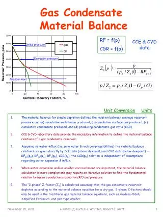
Condensate Recovery Equipment. What happens if you don’t get water out of your system. Corrosion Erosion Loss of efficiency Water Hammer. ( CO 2 + H 2 O = H 2 CO 3 ). Subcooled Condensate + CO2 Forms Carbonic Acid. Corrosion.

E N D
What happens if you don’t get water out of your system Corrosion Erosion Loss of efficiency Water Hammer
( CO2 + H2O = H2CO3 ) Subcooled Condensate + CO2 Forms Carbonic Acid Corrosion Cooled condensate and CO2 form a weak acid that attacks pipes.
Erosion Water is a steam system removes the protective oxide layer of the pipe wall.
Loss of Efficiency Heat transfers through water less efficiently
Water Hammer • Show Video
Total Cost of Condensate Condensate Wasted = Money Wasted Wasted Heat = 24.4% Wasted Water = 3.5% Water Treatment Cost = 1.0% Total Waste = 28.9% of steam production cost (Example above is for lost Condensate at 300 psig, 20 bar)
Cost of Lost Heat Sensible Heat = 395 btu/lb, 214 kcal/kg = 32% Latent Heat = 808 btu/lb, 454 kcal/kg = 68% Total Heat = 1203 btu/lb, 668 kcal/kg = 100% Assume total discard of condensate replaced with 50°F, 10°C water Wasted Condensate = 395 btu/lb, 214 kcal/kg Replacement Water = 50 btu/lb, 10 kcal/kg Wasted Heat = 345 btu/lb, 204 kcal/kg 204/668 x 100 = 30.5% of total heat in steam Heat (fuel) = approximately 80% of steam production cost 30.5 x 0.8 = 24.4% of steam production cost lost
PROCESS HEAT TRANSFER and CONDENSATE RECOVERY THE CAUSE AND EFFECT OF VARIOUS DESIGN CONCEPTS
Q = U • A •Δ T Q = HX Design Load (BTU/Hr) U = Manufacturer’s Heat Transfer Value (BTU/ft2/°F/Hr) A = Heat Transfer Surface Area (ft2) DT = (Ts – T2) Approaching Temperature (°F) Ts = Operating Steam Temperature (°F) T2 = Product Outlet Temperature (°F)
Q = GPM • 500 • SG • SH • ΔT Q = HX Performance Load (BTU/Hr) GPM = Product Flow (Gallons/Minute) 500 = 60minutes/hr x 8.32 lbs/gallon (499 actual) SG = Specific Gravity of Product SH = Specific Heat of Product ΔT = Product Temperature Rise (°F)
IN THEORY Q (Design) = Q (Performance)
IN REALITY Q (Design) for the heat exchanger will include a factor for fouling and potentially a factor for future requirements. These factors combined usually result in 10-30% additional surface area…possibly higher!!
EXCHANGER VARIABLES • Oversurfacing • Fouled surface area • Non-condensable gases • Flooded surface area • Variable process inlet and outlet temperatures • Variable process flow rates • All variables change the BTU demand on the heater, changing the pressure and temperature requirements of the heat transfer media
FOULED SURFACE AREA • Decreases the heat transfer efficiency of the tube bundle • Inherently causes adjustments in the pressure and/or temperature of the heat transfer media being supplied to the exchanger • Resulting in more surface area required…Increasing BTU transfer rate • Higher steam pressure from the inlet control valve decreases the efficiency of the heat exchanger. Higher pressure lacks the same heat content of lower pressure. Energy consumption will increase while production levels remain the same
BTU LOSS FROM SCALE SCALE THICKNESS % LOSS BTU 1/16” 13% 1/8” 22% 1/4” 38% 3/8” 50%
NON CONDENSABLE GASES • Non-condensable gases occupy valuable steam space • Creates a reduction of heat transfer surface area due to its insulating properties • Increases the potential for carbonic acid formation • Excessive amount can air-bind the heat exchanger
FLOODED SURFACE AREA • Promotes corrosion and fouling • Can produce damaging water hammer • Decrease the available surface area for heat transfer • Poor process temperature control
HEAT EXCHANGER LEVEL CONTROL
LEVEL CONTROL • Level control systems flood exchangers to reduce the amount of useable surface area for BTU transfer. • Exchangers run flooded due to the control valve on the condensate outlet, modulating to maintain the desired process outlet temperature.
Q = U • A •Δ T Q = Operating Load (BTU/Hr) VARIABLE U = Heat Transfer Value (BTU/ft2/°F/Hr) CONSTANT A = Heat Transfer Surface Area (ft2) VARIABLE DT = (Ts – T2) Approaching Temperature (°F) CONSTANT Ts = Operating Steam Temperature (°F) CONSTANT T2 = Product Outlet Temperature (°F) CONSTANT
Q = U • A •Δ T LEVEL CONTROL
LEVEL CONTROLLED HX Constant High Pressure Steam Supply Level Controller Hot Product Out Cold Product In High Pressure Condensate Return Level Controller Valve
LEVEL CONTROL HX • This is a common heat exchanger control scheme when high pressure steam (usually superheated and >300psig) is the energy source. It is also used when the condensate load exceeds the capacity of available steam trap designs. • Most applications occur in the refining, chemical, and utility industry. • Operation: Heat exchange is a function of the level of condensate in the heat exchanger shell (product is in the tubes). Exposed (dry) tubes have a higher “U” (btu/ft²°F) value than flooded (wet) tubes allowing higher transfer of energy from the steam to the product.
LEVEL CONTROLLED HX – HIGH LOAD Constant High Pressure Steam Supply Level Controller Hot Product Out Cold Product In High Pressure Condensate Return Level Controller Valve
LEVEL CONTROL HX – HIGH LOAD • HIGH PROCESS HX REQUIREMENT • Operation: All tubes exposed (dry) resulting in a high “U” (btu/ft²°F) value than flooded (wet) tubes allowing higher transfer of energy from the steam to the product. • “U” value for steam to heavy oil - 70 btu/ft²°F • “U” value for steam to molasses - 70 btu/ft²°F • “U” value for steam to molten sulfur - 60 btu/ft²°F • “U” value for steam to asphalt - 50 btu/ft²°F • “U” value for steam to light oil - 90 btu/ft²°F • “U” value for steam to watery solution - 225 btu/ft²°F
LEVEL CONTROLLED HX – LOW LOAD Constant High Pressure Steam Supply Level Controller Hot Product Out Cold Product In High Pressure Condensate Return Level Control Valve
LEVEL CONTROL HX – LOW LOAD • LOW PROCESS HX REQUIREMENT • Operation: Tubes flooded (wet) resulting in a lower “U” (btu/ft²°F) value than exposed (dry) tubes causing lower transfer of energy from the steam to the product. • “U” value for water to heavy oil - 9 btu/ft²°F • “U” value for water to molasses - 11 btu/ft²°F • “U” value for water to molten sulfur - 8 btu/ft²°F • “U” value for water to asphalt - 6 btu/ft²°F • “U” value for water to light oil - 20 btu/ft²°F • “U” value for steam to watery solution - 120 btu/ft²°F
POTENTIAL PROBLEMS • Heavy scaling resulting in loss of heat transfer performance • Damaging water hammer • Tube sheet failures due to thermal stress • Slow reaction to changing process conditions, poor turndown • High maintenance on level control valve
HEAT EXCHANGER SUPERHEATED STEAM
PROPERTIES OF SUPERHEATED STEAM SUPERHEATED STEAM PROPERTIES Specific Volume (cu ft/lb)(%incr) 1.16 1.47(21%) 0.72 0.86(16.3%) 0.91(20.8%) Total Heat¹ (btu/lb)(%incr) 781 884(11.6%) 728 810(10.1%) 871(16.4%) °F 445SAT 600SH 492SAT 600SH 700SH Psig 400 400 650 650 650 ¹Total Heat excludes Heat of Saturated Liquid, Sensible Heat
SUPERHEAT EXAMPLE HEAT EXCHANGER –using Saturated & Superheated Steam 650psig@492F(saturated) vs. 650psig@700F(superheated) Heat exchanger requirement – 3,000,000 lbs/hr Heating oil from 300°F to 400°F Heat transfer coefficient (“U” value) for steam to oil – 3.5 btu/ft²·hr·°f (SH) 26.5 btu/ft²·hr·°f (SAT) Calculate surface area required – Superheat(10.6% of total steam energy) Q = U·A·ΔT(LMTD) (3,000,000)(0.106) = (3.5 btu/ft²·hr·°f )(A)(210°LMTD) A = 433 ft² required to absorb superheated steam energy (3,000,000)(0.894) = (26.5 btu/ft²·hr·°f)(A)(140°LMTD) A = 723 ft² required to condense saturated steam energy TOTAL SURFACE AREA REQUIRED – 1156 FT²
SUPERHEAT EXAMPLE HEAT EXCHANGER – using only Saturated Steam 650psig@492F(saturated) Heat exchanger requirement – 3,000,000 lbs/hr Heating oil from 300°F to 400°F Heat transfer coefficient(“U” value) for steam to oil – 26.5 btu/ft²·hr·°(SAT) Calculate surface area required – Saturated Steam Q = U·A·ΔT(LMTD) 3,000,000 = (26.5 btu/ft²·hr·°f)(A)(140°LMTD) A = 809 ft² required to condense saturated steam energy TOTAL SURFACE AREA REQUIRED – 809 FT² 30% less when only utilizing saturated steam
HEAT EXCHANGER-SH Superheated steam is of little value when utilized in heat transfer/heat exchanger applications. • It gives up little heat energy until it has cooled to saturation temperature and can utilize the latent heat. • Requires larger heat transfer area and sometimes requires larger diameter distribution piping. • Creates uneven temperature gradients potentially causing process control problems or fouling of heat exchanger surfaces.
HEAT EXCHANGER STEAM VALVE CONTROLLED HX
STEAM VALVE CONTROLLED HX • This is a common heat exchanger control scheme for all steam pressures as the energy source • A condensate return system may be required • Applications occur in the refining, chemical, and utility industry as well as the food and institutional markets • Operation: Heat exchange is a function of the steam pressure and flow through the steam control valve feeding the heat exchanger shell (product is in the tubes). The steam valve modulates (throttles) to maintain variable process heat transfer requirements
Q = U • A •Δ T Q = Operating Load (BTU/Hr) VARIABLE U = Heat Transfer Value (BTU/ft2/°F/Hr) CONSTANT A = Heat Transfer Surface Area (ft2) CONSTANT DT = (Ts – T2) Approaching Temperature (°F) VARIABLE Ts = Operating Steam Temperature (°F) VARIABLE T2 = Product Outlet Temperature (°F) CONSTANT
Q = U · A ·Δ T STEAM VALVE CONTROL
VALVE CONTROLLED HX Modulating Control Valve Temperature Controller Steam Supply Hot Product Out Cold Product In Steam Trap Condensate Return
STEAM CONTROL HX • PROCESS HX REQUIREMENT • Operation: All tubes exposed (dry) resulting in a high “U” (btu/ft²°F) value than flooded (wet) tubes allowing higher transfer of energy from the steam to the product. Control valve modulates (throttles flow) to maintain product heat transfer requirements. • “U” value for steam to heavy oil - 70 btu/ft²°F • “U” value for steam to molasses - 70 btu/ft²°F • “U” value for steam to molten sulfur - 60 btu/ft²°F • “U” value for steam to asphalt - 50 btu/ft²°F • “U” value for steam to light oil - 90 btu/ft²°F • “U” value for steam to watery solution - 225 btu/ft²°F
STEAM VALVE CONTROL • Allows the exchanger to run at the lowest possible steam pressure, which maximizes energy efficiency due to latent heat content. • Less energy consumed for the same amount of product produced.
ADVANTAGES • Minimal scaling or loss of heat transfer surface • Longer on-line service life • Less damage due to corrosion and thermal stress • Quick reaction to changing process conditions, greater turndown • Lower overall maintenance
PROCESS DESIGN SUMMARY • Utilize all heat transfer surface area • Minimize corrosion and fouling by keeping the exchanger dry • Eliminate non-condensable gases • Quick reaction to changing process conditions, greater turndown • By design, utilize the lowest pressure steam possible and gain more latent heat content per pound of steam condensed
Pump Trap Applications • Process Heat Exchangers • Separators • Tank Coils • Distillation Columns, pressure and vacuum • Condensate Drum – Flash Tanks • Open Vented Systems • Closed Loop Applications
Condensate Recovery Systems Armstrong’s condensate pumps offer effective recovery of hot condensate • Self-actuated, non-electric • Condensate pump trap packages
Mechanical Pumps • No seals, motors or impellers which frequently fail • Low maintenance • Sized for actual condensate load • Can be used in closed loop applications • Conserve flash steam • Returns condensate hotter in closed-loop arrangement which: • Reduces likelihood of H2CO3 (carbonic acid) • Greater overall efficiency