Download
1 / 90
1.15k likes | 1.67k Views
Radio Receivers. Al Penney VO1NO. Role of the Receiver. The Antenna must capture the radio wave. The desired frequency must be selected from all the EM waves captured by the antenna. The selected signal is usually very weak and must be amplified.

E N D
Radio Receivers Al Penney VO1NO
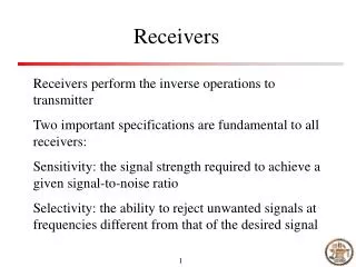
Role of the Receiver • The Antenna must capture the radio wave. • The desired frequency must be selected from all the EM waves captured by the antenna. • The selected signal is usually very weak and must be amplified. • The information carried by the radio wave, usually an audio signal, must be recovered – Demodulation. • The audio signal must be amplified. • The amplified audio signal must then be converted into sound waves using a speaker or headphones.
The 3 S’s of Receivers • Sensitivity • Selectivity • Stability
Sensitivity • Refers to the minimum signal level that the receiver can detect. • Measured in Microvolts or fractions of Microvolts at 50 Ohm, or dbm - db below 1 mW at 50Ω, e.g. - 130 dbm. • Sensitivity given as “MDS” (minimum discernable signal) or 10db S/N (signal to noise ratio) or S+N/N ratio. • The greater the sensitivity (ie: the smaller the number of microvolts) the weaker a signal it can receive.
Sensitivity • Very weak signals can be received – sensitivity is generally not an issue with modern receivers. • Between 1.7 and 24.5 MHz on SSB, the Kenwood TS-870 has a sensitivity of 0.2 microvolts or less.
Selectivity • Refers to the receiver’s ability to separate two closely spaced signals. • The more selective a receiver, the narrower the bandwidth and/or the steeper the filter skirt.
Selectivity • Specified as the bandwidth at 6 dB attenuation, and at 60 dB attenuation (ie: the –6 dB and –60 db points). • Filter Skirt steepness is perhaps THE key characteristic that separates the boys from the men in HF receiver design! • Example: On SSB the Kenwood TS-870 has a selectivity of 2.3 kHz at – 6 dB and 3.3 kHz at – 60 dB. This is a very selective receiver.
Actual Receiver Selectivity Filter Skirt
Stability • The receiver’s ability to remain on a frequency for a period of time. • Unintended change in frequency is called drift. • Specified as number of Hz drift over a period of time after warmup, or as ppm (part per million) for more modern radios. • Not an issue for modern receivers, but is a consideration for older designs, especially those using vacuum tubes.
Other Receiver Characteristics • Frequency precision: ability to determine the frequency. • Resettability: ability to return to a frequency. • Interference rejecting features: filters, DSP, noise blanker, noise limiter, RF preselector. • Dynamic range: range of signal strength through which the receiver operates properly.
Cross Modulation • Cross Modulation occurs when a strong signal is too powerful for the receiver’s front end (first RF Amplifier) to pass through without distortion. • It results in the wanted signal being Amplitude Modulated by the strong unwanted signal ie: the unwanted signal can be heard on top of the wanted signal.
Curing Cross Modulation • To prevent cross modulation, many receivers have an Attenuator that inserts a resistive pad (circuit) between the antenna and the receiver. • This weakens the strong signal enough that it no longer causes problems. • If the interfering signal is out of the band altogether, then an appropriate filter between the antenna and the receiver may also help. • FM receivers are immune to Cross Modulation as they are unaffected by amplitude variations on received signals.
Intermodulation • “Intermod” is sometimes incorrectly called Cross Modulation, but is a different phenomena. • It is the result of two or more signals of different frequencies being mixed together, forming additional signals at frequencies that are not, in general, at harmonic frequencies (integermultiples) of either. • The mixing usually takes place inside the receiver, but can even take place at rusty fence joints! • Very prevalent problem on 2M and 70cm FM when driving through downtown!
270 MHz 275 MHz 280 MHz 265 MHz
Images • Signals on a different frequency than the one tuned to, but which are received anyway. • Occurs because of the frequency conversions that are conducted within the receiver. • Image rejection is specified in dB. • The image rejection specifications for the Kenwood TS-870 are 80 dB or greater.
Natural Noise • Natural noise, called QRN, is also called Static. • It comes from objects in the galaxy that radiate RF energy, and from natural phenomena such as lightning. • The presence of natural noise sets the Noise Floor for the band in question at that particular time, and appears as a steady hiss. • Lightning appears as a burst of static, and can be dealt with to some degree by noise limiters.
Man-Made Noise • Also called QRM, Man-Made Noise generally comes from sparking equipment, and also from equipment that generates RF. • Some countries use HF radars that produce sharp pulses. • The best solution to most man-made noise is to eliminate it at the source, as it is often close to home. • Start at home, and then search the neighborhood, using a portable receiver to track down the noise. • Digital Signal Processing (DSP) is of great assistance in reducing QRM.
Receiver Limitations • It does no good to make HF receivers any more sensitive – they are already sensitive enough to hear the natural noise floor, and cannot hear anything below that level anyway. • Any component that generates gain also generates internal noise – it is unavoidable! • So, while the noise floor on VHF and UHF is much lower than HF, the quality of the active device (transistor) in the front end of the receiver determines the sensitivity of the system.
Signals and Noise • Another way to specify the sensitivity of a receiver is to express how many microvolts of signal are required to give a certain Signal to Noise Ratio (SNR). • Some use the Signal + Noise to Noise Ratio, or (S+N)/N. • These ratios are specified in dB.
Can we Increase Selectivity? • While it is possible to add filters (either discrete or virtual using DSP techniques) to increase selectivity, remember that every mode has a defined bandwidth. • If the selectivity is too wide, excess noise will be received. If too narrow however, the complete signalwill not be received. • CW filters of 250 Hz are common, but going too narrow will result in “ringing”. • Human voice requires a range of 300 – 2700 Hz. Using too narrow a filter will make the voice unintelligible.
Frequency Calibration • YOU are responsible for ensuring that you operate within the Amateur bands! • Radio dials can be analog or digital. • DO NOT assume that they are always correct! • Older radios use Crystal Calibrators to enable you to check the accuracy of the dial. • Newer, synthesized, radios use a master time base in the microprocessor to derive frequency information. If that time base is off, so will the calibration. • Use WWV / WWVH to calibrate your radio.
AM Demodulation Signal Diode Action Low Pass Filter
Tuned Radio Frequency Receiver • A Tuned Radio Frequency (TRF) receiver has several RF amplifier stages followed by detector and audio amplifier stages. • Each RF amplifier stage must be tuned individually. • This is a very cumbersome process! • For technical reasons, it is also difficult to achieve sufficient selectivity as the frequency increases.
Tuned Radio Frequency Receiver Antenna BPF BPF BPF Amp Amp Amp Det Spkr
Regenerative Receiver • High sensitivity • High selectivity (for weaker signals) • Poor stability • Poor immunity to overload • Mediocre resettability / logging • Generates a signal that can cause interference to others. • Cheap + easy to build! • Best performance requires careful design
The Superheterodyne Receiver • In 1918 Major Edwin Armstrong developed the Superheterodyne receiver to correct the problems of the TRF radio. • It mixes an incoming signal with a locally generated RF signal to produce an Intermediate Frequency (IF). • That IF is then amplified, detected and turned into sound. • The Superhet is still the most popular form of receiver, accounting for 99% or more!
Superheterodyne Receiver Antenna Radio Frequency Amplifier Mixer Filter High Frequency Oscillator Intermediate Frequency Amplifier Speaker Or Headphone Audio Frequency Amplifier Detector
Superheterodyne Receiver Antenna Radio Frequency Amplifier Mixer Filter High Frequency Oscillator Intermediate Frequency Amplifier Speaker Or Headphone Audio Frequency Amplifier Detector
Antenna • While technically the antenna picks up a wide range of frequencies, in practice some antennas are more narrow-banded. • Resonant antennas eg: a half-wave dipole, are better able to pick up signals around their design frequency. • Non-resonant antennas eg: Rhombics, can be used over a much broader frequency range.
Superheterodyne Receiver Antenna Radio Frequency Amplifier Mixer Filter High Frequency Oscillator Intermediate Frequency Amplifier Speaker Or Headphone Audio Frequency Amplifier Detector
Radio Frequency Amplifier • The RF amplifier takes the weak signals from the antenna and amplifies them. • This is usually a fairly broadband amp. In better radios it consists of a number of separate modules that cover individual bands. These modules would be selected automatically as the radio is tuned. • Older radios had a manually tuned continuous preamplifier. • This stage does have tuned circuits to help reject strong out-of-band signals that could cause Cross Modulation.
Superheterodyne Receiver Antenna Radio Frequency Amplifier Mixer Filter High Frequency Oscillator Intermediate Frequency Amplifier Speaker Or Headphone Audio Frequency Amplifier Detector
HF Oscillator and Mixer • The HF Oscillator, more usually called the Local Oscillator, generates an RF signal that is higher or lower than the desired receive frequency by an amount called the Intermediate Frequency. • It mixes with the signal from the RF Amp inside the Mixer. • Output from the mixer is the sum and difference of the two signals. • One of those two signals is the Intermediate Frequency. The choice is an engineering decision.
Superheterodyne Receiver Antenna Radio Frequency Amplifier Mixer Filter High Frequency Oscillator Intermediate Frequency Amplifier Speaker Or Headphone Audio Frequency Amplifier Detector
Filter and IF Amplifier • The Filter can be mechanical, crystal or ceramic. Newer radios employ a synthetic filter using Digital Signal Processing (DSP) techniques. • It filters out not just the non-IF signal, but is also the primary location where selectivity is obtained. • The IF Amp can consist of several stages that amplifie the IF signal. Because the IF has been pre-defined by the receiver’s design, the IF amp does not need to be tuned after calibration by the manufacturer. • A total of 40 – 80 dB gain.
Receiver Filters • Receivers often have several filters that can be switched in as required by the mode. • Examples of the filter widths and the usual mode they would be used for are: • 250 Hz CW (for severe interference) • 500 Hz CW (for more relaxed conditions) • 2.4 kHz SSB • 6 kHz AM, possibly SSB if band is not busy
Superheterodyne Receiver Antenna Radio Frequency Amplifier Mixer Filter High Frequency Oscillator Intermediate Frequency Amplifier Speaker Or Headphone Audio Frequency Amplifier Detector
Detector Stage • The amplified IF signal is sent to the Detector, where it is rectified and the RF filtered out. • This leaves only a weak audio signal which is sent to the AF amplifier before going to the speaker or headphones.
AM Demodulation IF Transformer