Download
1 / 19
190 likes | 300 Views
End-cap Mechanics FDR Cooling Structures. Steve Temple, RAL. 1 November 2001. End-Cap Disc Services Cooling Structures. Full details - See ATL-IS-ER-0021 Cooling Circuit Layout 3 circuits per quadrant - corresponding to inner, middle and outer module rings

E N D
End-cap Mechanics FDRCooling Structures • Steve Temple, RAL 1 November 2001 CLRC
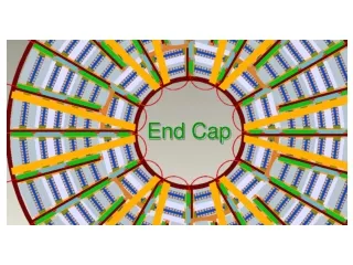
End-Cap Disc ServicesCooling Structures • Full details - See ATL-IS-ER-0021 • Cooling Circuit Layout • 3 circuits per quadrant - corresponding to inner, middle and outer module rings • 3 separate Inlets, 3 outlets are manifolded at patch panel • Outer and middle module Circuits - Two point cooling • Inner module circuit - Single point cooling • Bend radii (inner) kept to 5 times OD i.e. 18.7 mm • Cooling Component Materials/Joining Techniques • C-C cooling blocks • CuNi pipe - 3.6mm ID, 70 µm Wall • Cu plating (sputter coat + electroplate) of cooling blocks enables soft soldering to cooling pipe CLRC
End-Cap Disc ServicesCooling Structures • Mechanical Requirements • Position modules to a positional tolerance of 134 microns (diameter) in the R-phi direction, for one module relative to its neighbour • Provide co-planar mounting surfaces for modules • Minimise forces transferred to the support structure i.e. carbon fibre disc • Operational for 10 years • Lowest possible mass • Thermal Requirements • To ensure the highest temperature of any part of the silicon on a module doesn’t exceed -7 °C CLRC
End-Cap Disc ServicesCooling Structures • Cooling Pipe Circuit Design • CuNi material chosen for its excellent resistance to corrosion, and its excellent solderability • ‘Wiggly’ pipe Layout reduces forces on disc from thermal contractions and pipe manufacturing tolerance • Thermal Contraction Forces Forces calculated using an FE model, using following material properties and boundary conditions : E=152 GPa, = 12e-6/K, T=50K • Pipe Manufacturing Tolerances Deviation of pipe bend centres from nominal positions kept to a minimum, through tooling design In addition stress relieving of manufactured circuits is proposed - testing is planned in next round of prototyping CLRC
End-Cap Disc ServicesCooling Structures Inner Circuit CLRC
End-Cap Disc ServicesCooling Structures Outer Circuit CLRC
End-Cap Disc ServicesCooling Structures Middle Circuit CLRC
End-Cap Disc ServicesCooling Structures • Cooling Pipe Prototyping • First prototype - Inner cooling circuit for system test • Old circuit design - Internal bend radii of 14mm • Ice used as filler material • Custom made pipe bender designed and manufactured • Manufactured at RAL CLRC
End-Cap Disc ServicesCooling Structures • Cooling Pipe Prototyping (Cont’d) • Second prototype - Single U shaped bend • Internal bend radii of 20mm - 5 x OD • Cerobend used as filler material • Swaged ends - enables low mass joining of pipes • Manufactured by established pipe bending company CLRC
End-Cap Disc ServicesCooling Structures • Cooling Block Design • Primary Cooling Block Thermal Design • C-C material chosen for good thermal conductivity - 300 W/m2K (fibre direction), 50 W/m2K (transverse direction) • Fibre orientation optimised • Straight split corresponding to hybrid and silicon • Further details see thermal performance Mechanical Design • Machined module location boss • Planar module mounting surface wrt block mounting surface • Accurate cooling block height CLRC
End-Cap Cooling StructuresCooling Block Design • Cooling Block Design (Cont’d) • Second Point Cooling Blocks Thermal Design • C-C material chosen for good thermal conductivity - 300 W/m2K (fibre direction), 50 W/m2K (transverse direction) • Fibre orientation optimised Mechanical Design • As primary cooling block • Second Point Mounting Blocks Thermal Design • No thermal requirements - Made from low mass PEI polymer Mechanical Design • As primary cooling block CLRC
End-Cap Cooling StructuresCooling Block Design • Cooling Block Prototyping • Two prototyping exercises (old and current design) • Several manufactured, metrology checked to assess ability to machine key features within appropriate tolerances • 3mm OD location boss • Parallelness between bottom and top surfaces • Block height dimension CLRC
End-Cap Disc ServicesCooling Structures • Cooling Block Prototyping (Cont’d) • Current cooling block design metrology results • Improvements to design for machining operations simplification identified CLRC
End-Cap Disc ServicesCooling Structures • Joining of C-C Blocks to Cooling Pipe • Soldering of cooling blocks to pipe • Good thermal joint • Good mechanical joint - Soldered joint sample (using swaged end) undergone helium vacuum leak test • Standard SnPb (60/40) solder with non-corrosive Castolin 197 flux. • Requires Cu plating of C-C block • Cu Plating of C-C Blocks • Plating trials show good adhesion to C-C base material achieved by : Cleaning, Cu Sputtering, Cu Electroplating and Au Flash (to prevent copper oxidisation) • 15 micron Cu plating followed by 2 micron Au flash CLRC
End-Cap Disc ServicesCooling Structures • Cooling Structure Precision Assembly • To achieve positional tolerances required a precision assembly technique is performed during the disc services to disc assembly stage • This involves a precision rotary stage (r-phi) and an alignment arm (providing radial position) • Details see ATL-IS-ER-0022 CLRC
End-Cap Disc ServicesCooling Structures • Cooling Structure Precision Assembly (Cont’d) • Blocks are required to be positioned in r-phi with a positional tolerance of 66 microns - Out of 134 micron error budget • Results show this is readily achievable using this method CLRC
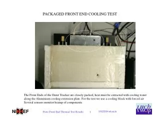
End-Cap Disc ServicesCooling Structures • Thermal Performance • Extensive prototype testing and thermal simulation carried out on the Baseline Design (see ATL-IS-ER-0009) • Full cooling quadrant (3 circuits) manufactured and tested on evaporative cooling rig • Dummy thermal module mounted on sector and tested • Successfully demonstrated a coolant temperature of -20 to -22 °C was sufficient to keep the inner module below -7 °C. • Design consisted of Aluminium Alloy cooling blocks joined to Aluminium cooling pipes. • Effect of material changes therefore need to be assessed CLRC
End-Cap Disc ServicesCooling Structures • Thermal Performance (Cont’d) • Assessment of cooling block material change • C-C block substituted into the simulation. Again boundary conditions - 4000 W/m2K @ -20C (7.5 W, 1W) • Minimal change on silicon side. Better performance on hybrid side. Al Tsil=-11.5°C C-C Tsil=-11.3°C Al THyb=-6.9°C C-C THyb=-8.4°C CLRC
End-Cap Disc ServicesCooling Structures • Thermal Performance (Cont’d) • Assessment of cooling pipe material change • Reduction in thermal conductivity and wall thickness results in reduction of convective heat transfer area. • However as htc increases with heat flux, this effect will be decreased. • Small scale prototype testing on an evaporative C3F8 cooling rig is planned CLRC