Download
1 / 49
490 likes | 498 Views
ATM-Asynchronous Transfer Mode Alpesh Desai SDE RTTC Ahmedabad. Contents. INTRODUCTION Difference between STM & ATM ATM protocol Different switching ATM interfaces and connections ATM network architecture. Contents. ATM type of switches ATM cell format, UNI/NNI format

E N D
ATM-Asynchronous Transfer ModeAlpesh DesaiSDE RTTC Ahmedabad
Contents • INTRODUCTION • Difference between STM & ATM • ATM protocol • Different switching • ATM interfaces and connections • ATM network architecture
Contents • ATM type of switches • ATM cell format, UNI/NNI format • ATM RM & layer functions • ATM benefits • ATM switch architecture • ATM services • Underlying transmission system for ATM
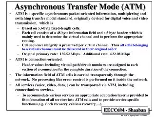
IntroductioNPre ISDN situation • 1stgeneration switches are dedicated to specific purposes such as telephony, facsimile and low speed data transfer used circuit switched telephone network. So high-speed data transfer over this network is not possible due to lack of bandwidth, flexibility, quality of transmission media and equipment.
ISDN situation • In 1984, ITU-T defined a new method called 2nd generation switch known as ISDN " a network that provides end to end digital connectivity to support a wide range of services including voice and non-voice service, to which users have access by a limited set of standard multipurpose UNI. For this, 2 interfaces called BRI or BRA (192Kbps) and PRI or PRA (2.048Mbps) are defined. By this, maximum transmission is restricted to 2Mbps only.
N-ISDN situation • With the basic bit rate of 64Kbps, the network can offer a maximum of 1.544Mbps (called T1 link) or 2.048Mbps (called E1 link). So, such a type of working is called N-ISDN.
B-ISDN situationIdea of B-ISDN was support to: • Add new high-speed channels to the existing channel spectrum. • Defines new broadband UNI (User Network Interface). • Rely on existing 64Kbps ISDN protocols and only modify or enhance them when absolutely unavoidable.
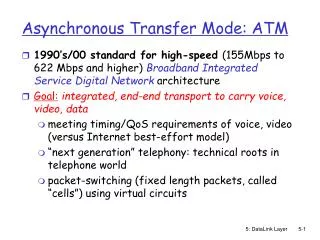
ATM situation • Mode means specific method or way. • Transfer means transmission and switching aspects. Switching by means of Cell Switching. Transmission by means of Primary rate of 155.52Mbps or above. • Asynchronous means information packets will be transferred based an irregular or random occurrence pattern as they are filled according to the demand.
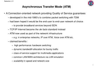
Definition:- • ATM is a high-speed networking standard designed to support both voice and data communications. • ATM is normally utilized by Internet service providers on their private long-distance networks. ATM operates at the data link layer over either fiber or twisted-pair cable.
Technique used in ATM :- • Packet switching technology. • Statistical multiplexing (another name of Asynchronous Time Division Multiplexing). • Cell Relay method.
ATM is convergence of a variety of services: • Low bandwidth and Very high bandwidth. • Synchronous and Asynchronous. • Voice, Video and Data. • Constant Bit Rate (CBR) and Variable Bit Rate (VBR). • Real-Time (RT) and Non-Real-Time (NRT). • Slotted and Pocketsize. • Switched and Non Switched.
ATM is an independent of Transmission medium, which means the medium can be Wire (Twisted Pair/Copper Pair/Co-axial/ Fiber) or Wireless. • ATM technology allows a variety of bit rates to be transported, with which sophisticated bandwidth management enables the network to be more efficient and at the same time, maintain a QoS (Quality of Service) that is custom suited to each other.
ATM Protocol • ATM is the protocol designed by ATM Forum and adopted by the ITU-T. • In ATM System, the packet size is fixed to 53 octets known as a CELL. Any type of traffic viz Voice, Data, Video, Synchronous or Asynchronous, Short or Long packets can be converted into ATM Cells by a process known as emulation. So ATM can also be called as Cell relaying technology or Cell switching technology. Primary rate of transmission in ATM is 155.52Mbps.
Switching • Circuit switching • Packet Switching • Two different approaches are available under packet switching. One is called Datagram approach and second is called Virtual circuit approach. The latter is used in ATM. • Message Switching
ATM utilizes no routing. Hardware devices known as ATM switches establish point-to-point connections between endpoints and data flows directly from source to destination.
The Structure of an ATM cell ATM defines two different cell formats: • UNI (User-Network interface) • NNI (Network-Network Interface).
ATM Connections • Permanent Virtual Connection (PVC) • Switched Virtual Circuit (SVC)
VP Switch/VC Switch • Most of the switches (Core switch) within typical ATM network are routed using VPI (VP switch). (i.e) The switching can be taken place by changing the VPI but keeping VCI within VPI intact. Such switches are called VP switch. If switching can be taken place by changing both the VPI and VCI, then such switches are called VC switch. The switches at end points (Edge switch) of the ATM network use both VPIs and VCIs
ATM Transmission Rates • At present, rate of transmission is 155Mbps called primary rate. Higher order is also possible in multiple of 4 times. • ATM Cell Format • ATM Cell consists of 2 fields called Header Field and Information Field. HEADER FIELD INFORMATION FIELD 5 OCTETS 48 OCTETS
GFC ( Generic Flow Control - 4 bits) • It is used to assist the customer network in the cell flow control, but not carried through the network. • VPI/VCI (Virtual Path Identifier-8 bits/Virtual Channel Identifier-16 bits) • This label identifies a particular virtual path and virtual channel or circuit on a transmission link. The switching nodes use this information and along with the routing information established at connecting setup, routes the cells to the appropriate output ports. The switching nodes changes the input value of VPI/VCI fields to new output values. Since VPI field is 8 bits (at UNI) and VCI has 16 bits field, a host can have theoretically 256 bundles, each containing up to 65,536 circuits. • 8 VPI bits provide 28 = 256 bundles • 16 VCI bits provide 216 = 65,536 circuits
CLP (Cell Loss Priority-1 bit) • Having one of the two values ‘0’ or ‘1’, the CLP indicates priority of a cell when the network element has to make the decision to drop the cell when its throughput bandwidth exceeds its transfer rate. • In congestion situations, cells with CLP =1 may be dropped and not transferred at all.
PTI (Payload Type Identifier-3 bits) • It identifies the payload type i.e. whether the cell payload contains user data or network information and also provides congestion identification. • HEC (Header Error Control-8 bits) • HEC code detects and corrects a single bit error or detects multi bit errors in the header field.
The Information Field does not contain all the 48 octets of user data. One or two octets are dedicated for administration and call sequence purpose. The first octet (after the overhead bits or Header octets) consists of three sub fields.The first bit is known as the convergence sub layer indicator (CSI). It is used to indicate whether the pointer is used or not. The next three bits are sequential number (SN) from 000 to 111 used to detect the type of cells. The next three bits are the Sequence Number Protection (SNP). It performs error detection on the CSI and SN sub fields. One bit is not used at present. • The second octet is optional and is used as a pointer to mark the start of long encapsulated messages.
The NNI cell format replicates the UNI format almost exactly, except that the 4-bit GFC field is re-allocated to the VPI field, extending the VPI to 12 bits..
ATM Reference Model • ATM functionality is organized in a stack of layers; each layer assigned a specific function. It consists of three planes called 1) User Plane 2) Control Plane 3) Management Plane
Management Plane: • All the management functions that relate to whole system are located in the management plane, which is responsible for providing coordination between all planes. • Two types of functions i) Layer Management ii) Plane Management.
Layer Management • Management functions relating to resources and parameters residing in its protocol entities. • Handles specific OAM information flow for each layer.
Plane Management • Management of all the planes for its proper functions. • Control Plane • Responsible for the call control and connection control functions. • These are all signaling functions for setup, supervise and release a call or connection. • User Plane • Deals with transport of user information, flow control and recovery from errors.
ATM Protocol Layers • ATM standard defined 3 layers. They are from top to bottom, the AAL (ATM Adaptation or Application Layer), the ATM Layer and the Physical Layer
Normally the end switches use all the 3 layers while the intermediate switches use only the bottom 2 layers.
Physical Layer • This Layer deals with issues related to physical connectivity of the transmission medium and transmission of ATM Cells. This layer is divided into 2 sub layers called • Physical Medium Dependent (PMD) • Transmission Convergence (TC)
Physical Medium Dependent (PMD) • It is the lowest sub layer and includes 2 functions namely • The PMD functions. • Bit timing functions.
The PMD functions. • Provide the bit transmission capability, including bit alignment. Line coding and if necessary, electrical/optical conversions is performed by this layer. In many cases PM will be an OFC. Other media such as coaxial and twisted pair cables are also possible. The transmission functions are medium specific.
Bit timing functions • Generation and reception of waveforms suitable for the medium, insertion and extraction of timing information, and line coding if required. • Transmission frame generation & recovery. • Transmission frame adaptation is responsible for all actions to adapt the Cell flow according to the payload structure of the transmission system (interface). • Cell delineation is the process, which allows identification of the Cell boundaries. • HEC sequence generation/verification. This is capable of detecting and correcting single bit error & detecting certain multiple-bit errors. • Cell rate decoupling. The insertion & discarding of idle Cells is called Cell rate decoupling.
ATM Layer This layer has got four functions: 1.Cell multiplex/demultiplex. VC and VP are multiplexed and demultiplexed. 2.VPI and VCI translation. 3.Cell header generation/extraction. 4.Generic Flow Control.
ATM Adaptation Layer (AAL) It has two functions. • Segmentation And Reassembly (SAR) • Convergence Sub layer (CS) • Service Specific Convergence Sub layer (SSCS) • Common Part Convergence Sub layer (CPCS)
AAL classification Based on Timing. Timing between source and destination required or not required. Real time services like voice & video required timing syn where as non-real time services like data transfer not required syn. Based on Bit rate. Bit rate constant or variable. Switched speech has CBR where as packet transfer has VBR. Based on Connection. Connection oriented or not. Based on Services offered. 5 layers called AAL1 to AAL5.
ATM Switch Type • Knockout switch, • Cross bar switch or single stage switch, • Shared memory switch, • Shared medium switch, • Fully interconnected switch, • Space division switch, • Banyan switch or multi stage switch, • Batcher-Banyan switch ( widely used ) • Sunshine switch.
Benefit Of ATM 2 Main benefits are • Traffic management • QoS
ATM Signallingconcepts • VPI=0 and VCI=5 is used for default signalling channel • VPI=X and VCI=Y is used for data transfer • Any VPI and VCI=5 can also be used for signalling • Switching is done according to the called number within signalling message • Signalling purpose to establish, release and maintain the user communication channel or path
ATM Switch Architecture • Input Modules (IMs) • Cell Switch Fabric (CSF) • Output Modules (OMs) • Connection Admission Control (CAC) • System Management (SM) • Muliplexer/Demultiplexer (Optional)
CELL • A Cell is a block of fixed length. • It is identified by a label at the ATM layer • Idle Cell • Valid Cell • Invalid Cell • Assigned Cell • Unassigned Cell • Meta signalling Cell • OAM Cell
Conclusion • The key to efficient utilization of the ATM networks is the integration of multiple services over a common infrastructure. Traffic management with QoS plays a significant role. ATM is going in a big way to play in different flavor like BB etc.
Thank You Any Questions ?