Download
1 / 19
230 likes | 388 Views
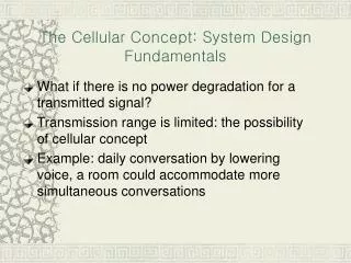
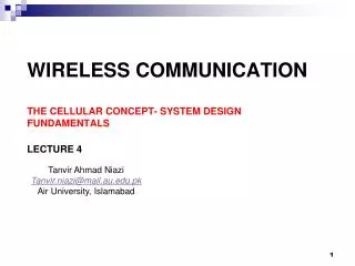
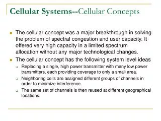
Cellular Fundamentals. Early Mobile Radio Single Tx, high power, and tall tower Low cost Large coverage area Small # users Poor spectrum utilization Cellular Concept Many base stations, lower power, and shorter towers Small coverage areas called “cells”

E N D
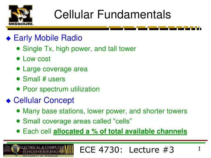
Cellular Fundamentals • Early Mobile Radio • Single Tx, high power, and tall tower • Low cost • Large coverage area • Small # users • Poor spectrum utilization • Cellular Concept • Many base stations, lower power, and shorter towers • Small coverage areas called “cells” • Each cell allocated a % of total available channels ECE 4730: Lecture #3
Cellular Fundamentals • Cellular Concept (continued) • Nearby (adjacent) cells assigned different channel groups • Minimize interference between neighboring base stations and mobile users • Same frequency channels may be reused by cells a “reasonable” distance away • Reused many times as long as interference between same channel (co-channel) cells is < acceptable level • Frequency reuse # users system cost *** A fixed # of channels serves a large # of users by reusing channels throughout coverage area *** ECE 4730: Lecture #3
Frequency Reuse/Planning • Design process of selecting & allocating channel groups to cellular base stations • Two competing/conflicting objectives: 1) Maximize frequency reuse in specified area 2) Minimize interference between cells • Cells • Base station antennas designed to cover specific cell area • Hexagonal cell shape assumed for planning • Simple model for easy analysis circles leave gaps! • Actual cell “footprint” is amorphous (no specific shape) • Contour where Tx successfully serves mobile unit ECE 4730: Lecture #3
Frequency Reuse/Planning • Base station location • Cell center omni-directional antenna (360° coverage) • Cell corners ?? not really! See Fig. 3.8, pg. 87 • Typically 3 sectored or directional antennas • Very common • Frequency reuse pattern • Cell Cluster group of N cells using complete set of available channels • Cluster pattern repeated M times over a service area to provide complete coverage ECE 4730: Lecture #3
Frequency Reuse Pattern N = 7 Cell Reuse Pattern A-G Unique Channel Groups M = 3 Cell Clusters Co-Channel Cells same channel group in different clusters ECE 4730: Lecture #3
Cell Layout • N cells/cluster • Hexagonal geometry connect without gaps • Specific values of N required for hexagonal geometry • N = i2 + i j + j2 where i, j 1 • Typical N values 3, 7, 12 (i, j = 1/1, 1/2, 2/2) • N = 4 also used (non-hexagonal cell shape) ECE 4730: Lecture #3
Co-Channel Cells • Move i cells along any chain of hexagons • Turn 60° CCW and move j cells along chain ECE 4730: Lecture #3
System Capacity • S: total # of duplex voice channels available for use in a given system (area)- determined by: • Amount of allocated spectrum (e.g. FCC) • Channel BW modulation format and/or standard specs (e.g. AMPS) • k: allocate a subset of S for each cell where k < S and S = k N • N: cluster size # of cells forming cluster • M : # of times a cluster is replicated in a service area • System Capacity = Total # Duplex Channels = C • C = M k N = M S ECE 4730: Lecture #3
System Capacity • For large system capacity : • Large M small cell size and/or small cluster size (N) • Why small N?? for a given area, a small cluster size translates to more clusters/area and M • Cluster size N and cell radius R determines : • Distance between co-channel cells (D) • Level of co-channel interference • Large N large D low interference small M low C !! • Frequency reuse factor = 1 / N • Each cell assigned k S / N ECE 4730: Lecture #3
System Capacity • Example: Given 30 MHz of spectrum for an FDD cell system using two 25 kHz SX channels for FDX operation, determine a reasonable distribution of control & voice channels for each cell in a cluster size of N = 7 if 0.5 MHz of spectrum is dedicated for control channel use. Assume omni-directional antennas (1 antenna/cell) • 30 MHz of total spectrum • FDX channel BW = 2 25 kHz = 50 kHz • Total # of duplex channels = 30 MHz / 50 kHz = 600 • Dedicated control channels (CC) = 0.5 MHz / 50 kHz = 10 ECE 4730: Lecture #3
System Capacity • Example (continued) : • S = # of duplex voice channels (VC) = 600 10 = 590 • # of VC/cell 590 / 7 84 • # of CC/cell 10 / 7 1 • Exact solution: 5 cells @ 84 VC & 2 cells @ 85 VC • Full utilization of voice channels • 1 CC/cell • Do not need more than 1 CC/cell for omni-directional antennas • extra CCs (e.g. 3) means that greater reuse distance will result less interference between cell control channels ECE 4730: Lecture #3
Channel Assignment • Goal is to minimize interference & maximize capacity • Lower interference allows smaller N to be used greater frequency reuse larger C • Two main strategies: Fixed or Dynamic • Fixed Assignment • Each cell allocated a pre-determined set of voice channels • Calls within given cell only served by unused cell channels • All channels used blocked call no service • Several variations • MSC allows cell to “borrow” VC from adjacent cell • Adjacent donor cell must have available VC to give ECE 4730: Lecture #3
Channel Assignment • Dynamic Assignment • Channels NOT allocated permanently • Call request serving base station MSC • MSC allocates channel “on the fly” • Allocation strategy considers • Probability of blocked call • Reuse distance (interference potential) • Channel frequency • Advantage: reduces call blocking, increases trunking capacity (not C), and increases voice quality ECE 4730: Lecture #3
Channel Assignment • Dynamic Assignment (continued) • Disadvantage: increases storage & computational load @ MSC • Requires real-time data from entire network on • Channel occupancy • Traffic distribution • Radio Signal Strength (RSS) of all channels ECE 4730: Lecture #3
Mobile Unit Handoff • Handoff : when a mobile unit moves from one cell to another while a call is in progress, the MSC must transfer (handoff) the call to a new channel belonging to new base station • New voice and control channel frequencies • Very important task often given higher priority than new call!! • Which is more annoying to customers? • Dropping call during middle of conversation • Blocking a new call request ECE 4730: Lecture #3
Mobile Unit Handoff • Minimum Useable Signal (MUS) • Lowest acceptable voice quality • Specified by system designers • Typical values 100 to 110 dBm • Handoff Threshold (HT) > MUS Level • Handoff Margin • = PHTPMUS • Carefully selected • too large unnecessary handoff MSC loaded down • too small not enough time to transfer call dropped! • Fig. 3.3, pg. 63 Note ECE 4730: Lecture #3
PHT PMUS PHT PMUS Illustration of Handoff at Cell Boundary ECE 4730: Lecture #3
R Ideal Cellular Coverage Less than R: only covered by BS A Greater than R: not covered by A. Only covered by BS in cell where mobile is located (e.g. B, C, D, etc.) G B F A C E D
R R` Real-World Cellular Coverage R: covered by both base station A & F R’: not covered by base station A or F G B F A Buildings or other sources of shadowing, fading, and path loss cause dead zones C E Actual Cell Model D