Download
1 / 35
380 likes | 511 Views
Electromagnetic Induction. previously:. Electric currents generate magnetic fields. If a current is flowing in a straight wire, you can determine the direction of the field with the (curly) right-hand rule: and calculate the field strength with the equation: B= 0 I/(2d)

E N D
previously: • Electric currents generate magnetic fields. If a current is flowing in a straight wire, you can determine the direction of the field with the (curly) right-hand rule: • and calculate the field strength with the equation: B=0I/(2d) • For a loop (which is a solenoid with one turn): B=0IN/(2R) (at the center of the loop) • For a long solenoid is long: B=0 I N/L (anywhere way inside) Electromagnetic Induction
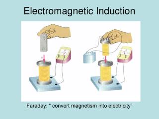
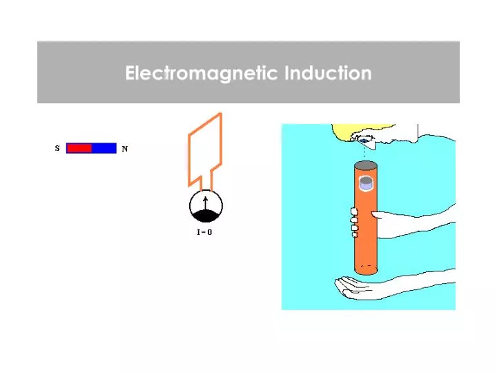
Electromagnetic Induction: • The reverse is true also: a changing magnetic field can generate an electric field. • This effect is called induction: In the presence of a changing magnetic field, an electromotive force (= “emf” = “voltage”) is produced. demo: coil and galvanometer Moving the magnet closer to the loop, or farther away, produces a current. If the magnet and loop are held stationary, there is no current. Electromagnetic Induction
Necessary definition: magnetic flux • A magnetic field with strength B passes through a loop with area A • The angle between the B-field lines and the normal to the loop is • Then the magnetic flux B is defined as: Units: Tm2 or Weber lon-capa uses Wb Electromagnetic Induction
example: magnetic flux • A rectangular-shaped loop is put perpendicular to a magnetic field with a strength of 1.2 T. The sides of the loop are 2 cm and 3 cm respectively. What is the magnetic flux? • B=1.2 T, A=0.02x0.03=6x10⁻⁴ m2, =0. • B=1.2 x 6x10-4 x 1 = 7.2x10⁻⁴ Tm • Is it possible to put this loop such that the magnetic flux becomes 0? • a) yes • b) no Electromagnetic Induction
Faraday’s law: • By changing the magnetic flux B in a time-period t a potential difference V (electromagnetic force ) is produced Warning: the minus sign is never used in calculations. It is an indicator for Lenz’s law which we will see in a bit. Electromagnetic Induction
changing the magnetic flux • changing the magnetic flux can be done in 3 ways: • change the magnetic field • change the area • changing the angle Electromagnetic Induction
example x x x x x x x x x x x x • a rectangular loop (A=1m2) is moved into a B-field (B=1 T) perpendicular to the loop, in a time period of 1 s. How large is the induced voltage? The field is changing: V=AB/t=1x1/1=1 V • While in the field (not moving) the area is reduced to 0.25m2 in 2 s. What is the induced voltage? The area is changing by 0.75m2: V=BA/t=1x0.75/2=0.375 V • This new coil in the same field is rotated by 45o in 2 s. • What is the induced voltage? The angle is changing (cos00=1 to cos450=1/22): V=BA (cos)/t=1x0.25x0.29/2=0.037 V Electromagnetic Induction
Faraday’s law for multiple loops • If, instead of a single loop, there are multiple loops (N), the the induced voltage is multiplied by that number: N S demo: loops. If an induced voltage is put over a resistor with value R or the loops have a resistance, a current I=V/R will flow resistor R Electromagnetic Induction
first magnitude, now the direction… • So far we haven’t worried about the direction of the current (or rather, which are the high and low voltage sides) going through a loop when the flux changes… N S direction of I? resistor R Electromagnetic Induction
Lenz’s Law • The direction of the voltage would always make a current to oppose the change in magnetic flux. When a magnet approaches the loop, with north pointing towards the loop, a current is induced. As a result, a B-field is made by the loop (Bcenter=0I/(2R)), so that the field opposes the incoming field made by the magnet. Use right-hand rule: to make a field that is pointing up, the current must go counter clockwise The loop is trying to push the magnet away demo: magic loops Electromagnetic Induction
Lenz’s law II • In the reverse situation where the magnet is pulled away from the loop, the coil will make a B-field that attracts the magnet (clockwise). It opposes the removal of the B-field. Bmagnet Binduced Bmagnet Binduced v v magnet moving away from the coil magnet approaching the coil Electromagnetic Induction
Be careful • The induced magnetic field is not always pointing opposite to the field produced by the external magnet. x x x x x x x x x x x x If the loop is stationary in a field, whose strength is reducing, it wants to counteract that reduction by producing a field pointing into the page as well: current clockwise Electromagnetic Induction
S S N N Binduced I Bmagnet demo magnet through cooled pipe • when the magnet passes through the tube, a current is induced such that the B-field produced by the current loop opposes the B-field of the magnet • opposing fields: repulsive force • this force opposes the gravitational force and slow down the magnet • cooling: resistance lower current higher, B-field higher, opposing force stronger vmagnet can be used to generate electric energy (and store it e.g. in a capacitor): demo: torch light Electromagnetic Induction
question x x x x x x x x x x x x A B A rectangular loop moves in, and then out, of a constant magnet field pointing perpendicular (into the screen) to the loop. Upon entering the field (A), a …. current will go through the loop. a) clockwise b) counter clockwise When entering the field, the loop feels a magnetic force to the … a) left b) right Electromagnetic Induction
The loop will try to make a B-field that oppose the one present, so out of the screen. Use second right-hand rule: counterclockwise. Method 1: Use first right hand rule with current and B-field that is present: left Method 2: The force should oppose whatever is happening, in this case, it should oppose the motion of the loop, so point to the left to slow it down. question x x x x x x x x x x x x A B A rectangular loop moves in, and then out, of a constant magnet field pointing perpendicular (into the screen) to the loop. Upon entering the field (A), a …. current will go through the loop. a) clockwise b) counter clockwise When entering the field, the loop feels a magnetic force to the … a) left b) right Electromagnetic Induction
I I v v v weak opposing force no opposing force strong opposing force Eddy current+demo • Magnetic damping occurs when a flat strip of conducting material pivots in/out of a magnetic field • current loops run to counteract the B-field • At the bottom of the plate, a force is directed the opposes the direction of motion x x x x x x x x x x x x x x x x x x x x x x x x x x x x x x B-field into the page Electromagnetic Induction
applications of eddy currents • brakes: apply magnets to a brake disk. The induced current will produce a force counteracting the motion • metal detectors: The induced current in metals produces a field that is detected. Electromagnetic Induction
A moving bar B-field into the page x x x x x x x x x x x x x x x x x x x x x x x x x x x x x x • Two metal rods (green) placed parallel at a distance d are connected via a resistor R. A blue metal bar is placed over the rods, as shown in the figure and is then pulled to the right with a velocity v. • a) what is the induced voltage? • b) in what direction does the current flow? And how large is it? • c) what is the induced force (magnitude and direction) on the bar? What can we say about the force that is used to pull the blue bar? R V d Electromagnetic Induction
answer B-field into the page x x x x x x x x x x x x x x x x x x x x x x x x x x x x x x • a) induced voltage? B: constant, cos=1 A/t=v x d so B/t=Bvd=induced voltage R V d • B) Direction and magnitude of current? • The induced field must come out of the page (i.e. oppose existing field). Use 2nd right hand rule: counter-clockwise • I=V/R=Bvd/R Electromagnetic Induction
answer II x x x x x x x x x x x x x x x x x x x x x x x x x x x x x x I • Induced force?: Direction? Method I: The force must oppose the movement of the bar, so to the left. Method II: Use first right hand rule for the bar: force points left. Magnitude?: Finduced =BIL (see chapter 19) = B x I x d This force must be just as strong as the one pulling the rod, since the velocity is constant. R V d Electromagnetic Induction
Doing work • Since induction can cause a force on an object to counter a change in the field, this force can be used to do work. • Example jumping rings: demo current cannot flow current can flow The induced current in the ring produces a B-field opposite from the one produced by the coil: the opposing poles repel and the ring shoots in the air application: magnetic propulsion, for example a train. Electromagnetic Induction
generating current. • The reverse is also true: we can do work and generate currents By rotating a loop in a field (by hand, wind water, steam…) the flux is constantly changing (because of the changing angle and a voltage is produced. t with : angular velocity =2f = 2/T f: rotational frequency T: period of oscillation demo: hand generator Electromagnetic Induction
Time varying voltage • Maximum voltage: V = N B A • This happens when the change in flux is largest, which is when the loop is just parallel to the field Vmax time (s) C -Vmax C B B A side view of loop A Electromagnetic Induction
Question • A current is generated by a hand-generator. If the person turning the generator increased the speed of turning: A) the electrical energy produced by the system remains the same B) the electrical energy produced by the generator increases C) the electrical energy produced by the generator decreased Electromagnetic Induction
The change of flux per time unit increases and thus the output voltage. Or one can simply use conservation of energy: More energy put into the system, more must come out question • A current is generated by a hand-generator. If the person turning the generator increased the speed of turning: • a) the electrical energy produced by the system remains the same • b) the electrical energy produced by the generator increases • c) the electrical energy produced by the generator decreased Electromagnetic Induction
Self inductance L • Before the switch is closed: I=0, and the magnetic field inside the coil is zero as well. Hence, there is no magnetic flux present in the coil • After the switch is closed, I is not zero, so a magnetic field is created in the coil, and thus a flux. • Therefore, the flux changed from 0 to some value, and a voltage is induced in the coil that opposed the increase of current I V Electromagnetic Induction
Self inductance II L • The self-induced current is proportional to the change in flux • The flux B is proportional to B. • B is proportional to the current through the coil. • So, the self induced emf (voltage) is proportional to change in current I e.g. Bcente r= 0 I N/length for a solenoid L inductance : proportionality constant Units: V/(A/s)=Vs/A usually called Henrys (H) Electromagnetic Induction
Induction of a Solenoid • flux of a coil: • Change of flux with time: • induced voltage: Electromagnetic Induction
An RL circuit R L I V A solenoid and a resistor are placed in series. At t=0 the switch is closed. One can now set up Kirchhoff’s 2nd law for this system: If you solve this for I, you will get: The energy stored in the inductor :W = ½ L I2 Electromagnetic Induction
R L I V RL Circuit II • When the switch is closed the current only rises slowly because the inductance tries to oppose the flow. • Finally, it reaches its maximum value (I=V/R) • When the switch is opened, the current only slowly drops, because the inductance opposes the reduction • is the time constant (s) energy is released energy is stored Electromagnetic Induction
R L I V question • What is the voltage over an inductor in an RL circuit long after the switched has been closed? • a) 0 b) V/R c) L/R d) infinity Electromagnetic Induction
R L I V Answer: Zero! The current is not changing anymore, so the change per unit time is zero and hence the voltage. question • What is the voltage over an inductor in an RL circuit long after the switched has been closed? • a) 0 b) V/R c) L/R d) infinity Electromagnetic Induction
R L I V • Use given L and R: time constant is 2x10⁻³ • maximum current (after waiting for some time): I=V/R=2 A • 0.75*2=2x(1-e-t/(L/R)) • 0.25=e-t/(L/R) so -1.39=-t/(L/R) and t=1.39 x 2x10-3=2.78x10⁻³ example • Given R=10 Ohm and L=2x10⁻² H and V=20 V. • a) what is the time constant? • b) what is the maximum current through the system • c) how long does it take to get to 75% of that current if the switch is closed at t=0 Electromagnetic Induction
lon-capa For question 9, note that the voltage over the inductor is constant and the situation thus a little different from the situation of the previous page. You have done this before for a capacitor as well… Electromagnetic Induction