Download
1 / 20
210 likes | 377 Views
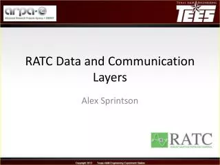
Substation RATC. Project Team: Mladen Kezunovic, Principal Investigator Gurunath Gurrala , Coordinator Ahad Esmaeilian , Ph.D. student Ahmad Abdullah, Ph.D. student Mohammad Tasdighi , Ph.D. student Payman Dehghanian , Ph.D. student . Plan & Progress. Future Work.

E N D
Substation RATC Project Team: Mladen Kezunovic, Principal Investigator Gurunath Gurrala, Coordinator AhadEsmaeilian, Ph.D. student Ahmad Abdullah, Ph.D. student Mohammad Tasdighi, Ph.D. student PaymanDehghanian, Ph.D. student
Plan & Progress Future Work Progress of tasks During the Period Completed deliverable During the Period
Task 1.3Cascade Event Detection Deliverable: In cases when existing relays miss-operate due to overload the new method operates correctly by detecting that there was no fault • Task 1.3 Test Plan 3 • LineFault Location - Use Case 302 • Test Case 3.3 – IEEE 73 & 118 Simulation results • Test Case 3.4 - Lab set-up with actual relays • Future Steps
Task 1.3 Test Plan 3 Use Case 302 is an Extension Use Case 301 - DEC 2010 Test Cases - TC 3.1& TC 3.2 Use Cases: UC-301 & UC-302
Line Fault LocationUse Case-302,Test Case 3.3 TC-3.3 : IEEE 118 & 73 Bus, 500 variations Changing fault distance, fault resistance, inception angle etc.) tested on both systems 118 BUS SYSTEM 73 BUS SYSTEM Location of Faults determined in all cases with less than 2% error. Goal Achieved: In case of Relay miss-operations the Fault Detection, Classification & Location Module accurately detects whether the Line is Faulted or not
Test Case 3.4Lab set-up with actual relays Using this setup the Line Fault Detection, Classification & Location Module’s capability is tested. This will be used to generate credible test data for demonstration.
Task 1.3Future Steps • Software development in C++ • Test cases using TVA data - Test Case 3.5 Jun Oct May July Aug Sep Cascade Event Detection software development in C++ and testing on TVA data
Task-1.5Management of Relay Settings Deliverable: Method for calculating settings for new topology 5x faster setting computation than using traditional relay setting coordination package (CAPE) • Task 1.5 Test Plan-5 • Parallel computations using Diakoptics- Use Case 501 • Test Case 5.1 - Results on IEEE 118 bus test system • Test Cases 5.2, 5.3 & 5.4 Impact on Settings • Brief Summary of Salient points about Relay Setting Procedures – Meeting at TVA on March 15th • Future Steps
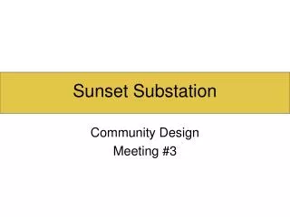
Task 1.5Test Plan 5 Use Case 501 Lines to be Switched Fast Settings Calculation Diakoptics ZBus Use Case 502 Relay Coordination Test Case TC 5.1 Use CAPE for Settings Existing Settings TVA Setting and Coordination Rules TVA Events New Settings Compare Impact Evaluation Test Case TC 5.5 Same “Success” List Vulnerable Test Cases TC 5.2, 5.3, 5.4
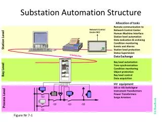
YBus1 Subsystem 1 YBus2 Subsystem 2 YBus3 Subsystem 3 Layer – 1 Diakoptics Based ZBus 1 Remote Bus faults, All lines in Service 2 Line-End faults on adjacent lines, all lines in service 3 Zone-1 Settings Layer – 2 Short Circuit Data Base & Zone-1 Settings Parallel computations using Diakoptics- Use Case 501 ZBus using Eqn (1) 1 Zone-2 Settings Subsystem-1 2 Zone-2 Settings Subsystem-2 3 Zone-2 Settings Subsystem-3 Layer – 3 Zone-2 Settings 1 Zone-3 Settings Subsystem-1 2 Zone-3 Settings Subsystem-2 3 Zone-3 Settings Subsystem-3 Layer – 4 Zone-3 Settings SuiteSparse 4.0.2 solver, Factorize Packege is Used
Test Case 5.1Results on IEEE 118 Bus Table I. ZBus calculation time, Diakoptics and Conventional Methods Table II. CAPE execution time Table III. Execution Time --- Diakoptics Approach Table IV. DiakopticsMathod vs. CAPE It is feasible to get more than 5X faster compared to CAPE
Test Cases 5.2, 5.3 & 5.4 Impact on Settings 130-134, 69-77, 82-83, 85-88, 99-100 3 lines share a common bus Lines in close proximity 131-133, 133-137, 133-33, 137-34, 93-94 Lines far away from each other 134-135, 20-21, 44-45, 64-65, 78-79 Very few zone 2 settings but more zone 3 settings need to be revisited. No of Relays affected beyond Zone-3 region are less
Brief SummaryMarch 15th TVA Meeting Test Case 5.5 Based on Recommendations Salient Points to be Noted 1. TVA is expected to provide 3-events in which they recalculated settings and changed the settings. 2. For each event TVA will provide the setting and coordination procedures followed and time taken for the task. 3. The procedures followed by TVA for setting and coordination of the selected relays in each event will be investigated for fast and accurate implementation using the developed techniques. 1.TVA sets one relay at a time and follows several procedures. 2. One relay setting and coordination session needs minimum 40 working hours. 3.CAPE is primarily used as a computational tool for short circuit values. 4.Whenever needed, groups are switched locally. Settings are changed locally by technicians. Success is when significant reduction in the time to implement the actual TVA setting and coordination procedures is achieved to meet RATC requirements
Task 1.5Future Steps • Comparing open source parallel sparse solver packages • Software Development in C++. • The TVA procedures will be investigated • for reduction in computational time • using the proposed method. Test Case 5.5 Jun Oct May July Aug Sep Management of Relay Settings Comparing open source sparse solvers. Software development in C++. Testing on TVA data
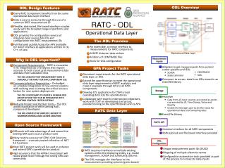
Circuit Breaker Reliability Monitoring Deliverable: Method for assessing breaker reliability based on condition based data from circuit breaker control circuit and establishing topology risk factors to be used as contingency matrix for substation topology switching • Task 1.7 Test Plan 4 & Test Cases • Circuit Breaker Failure Probability Assessment - Use Case 401 • Circuit Breaker Reliability Assessment for Switching - Use Case 403 • Test Case – 4.3 • Risk Analysis for CB Maintenance Prioritization – Use Case 402 • Future Steps
Task 1.7Test Plan 4 & Test Cases CB Measurements RATC Data Layer Static Model Data Risk to RATC: If the CBs are not good Enough then RATC implementation is Difficult. Multiple switching sequences are proposed And the lowest risk switching event will be Selected. Circuit Breaker Failure Probability Assessment Use Case 401 Risk to System: Frequent switching of CBs due RATC implementation may deteriorate CB Performance. So a security based Maintenance prioritization is proposed which if implemented will eventually improve the availability of CBs CB Maintenance Prioritization Use Case 402 Circuit Breaker Reliability Analysis for Switching Use Case 403 Risk Indices of Switching Sequence CB Maintenance Prioritization List
Circuit Breaker Failure Probability Assessment - Use Case 401Test Case 4.1 & Test Case 4.2 COMTRADE Signal Processing Required Timings Probability Distribution
Circuit Breaker Reliability Assessment for Switching Use Case 403, Test Case – 4.3 Erick’s Team Risk associated in completely switching a line Switching decision is based on the Risk in TWO SIDES line switching The END which has low Risk will be the side to be switched first Line 91 need to be selected for switching and TO END will be switched first
CB Maintenance Prioritization – Use Case 402Test Case 4.4 to Test Case 4.10 R I S K Probability Security violations (Over voltage and Over loading) due to any line, generator or load outages corresponding to Single CB mal-operation are considered as the consequence. R I S K Risk index alone cannot be used for maintenance prioritization because the CBs having low probability of failure with highest risk might be picked up as highest priority ones. The cost associated with re-dispatch to mitigate security violations due to each CB mal-operation can be obtained from the optimal power flow (OPF) OPF Cost
Task 1.7Future Steps • Circuit Breaker Reliability Assessment for Switching Extension to more cases on IEEE 73 bus system and IEEE 118 system • Software development in C++ • Testing on TVA system data – Test Case 4.1 & 4.2 Jun Oct May July Aug Sep CB reliability Monitoring Extension to more Switching cases,Softwaredevelopment in C++. Testing on TVA data