Download
1 / 15
150 likes | 250 Views
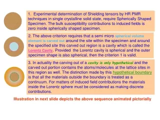
1. Experimental determination of Shielding tensors by HR PMR techniques in single crystalline solid state, require Spherically Shaped Specimen. The bulk susceptibility contributions to induced fields is zero inside spherically shaped specimen.

E N D
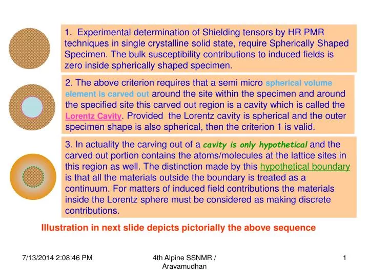
1. Experimental determination of Shielding tensors by HR PMR techniques in single crystalline solid state, require Spherically Shaped Specimen. The bulk susceptibility contributions to induced fields is zero inside spherically shaped specimen. 2. The above criterion requires that a semi micro spherical volume element is carved out around the site within the specimen and around the specified site this carved out region is a cavity which is called the Lorentz Cavity. Provided the Lorentz cavity is spherical and the outer specimen shape is also spherical, then the criterion 1 is valid. 3. In actuality the carving out of a cavity is only hypothetical and the carved out portion contains the atoms/molecules at the lattice sites in this region as well. The distinction made by this hypothetical boundary is that all the materials outside the boundary is treated as a continuum. For matters of induced field contributions the materials inside the Lorentz sphere must be considered as making discrete contributions. Illustration in next slide depicts pictorially the above sequence 4th Alpine SSNMR / Aravamudhan
1. Contributions to Induced Fields at a POINT within the Magnetized Material. HighResolution Proton Magnetic Resonance Experiment Only isotropic bulk susceptibility is implied in this presentation II I SphereσII=0 Calculate σIand subtract from σexp PROTON SHIELDING σexp MolecularσM+Region IσI+Region II σII σexp= σI +σM+σII - σI = Lorentz Sphere Contribution σI≡ σinter Bulk Susceptibility Effects 4th Alpine SSNMR / Aravamudhan
1. Contributions to Induced Fields at a POINT within the Magnetized Material. The Outer Continuum in the Magnetized Material Sphere of Lorentz Specified Proton Site Lorentz Sphere Lorentz Cavity The Outer Continuum in the Magnetized Material Inner Cavity surface Din Outer surface D out In the NEXT Slide: Calculation Using Magnetic Dipole Model & Equation: D out = -Din HenceD out + Din =0 The various demarcations in an Organic Molecular Single Crystalline Spherical specimen required to Calculate the Contributions to the induced Fields at the specified site. D out/in values stand for the corresponding Demagnetization Factors 4th Alpine SSNMR / Aravamudhan
2. Calculation of induced field with the Magnetic Dipole Model using point dipole approximations. Induced field Calculations using these equations and the magnetic dipole model have been simple enough when the summation procedures were applied as would be described in this presentation. Isotropic Susceptibility Tensor = σinter σ1 +σ2 +σ3 . . = 4th Alpine SSNMR / Aravamudhan
How to ensure that all the dipoles have been considered whose contributions are signifiicant for the discrete summation ? That is, all the dipoles within the Lorentz sphere have been taken into consideration completely so that what is outside the sphere is only the continuum regime. The summed up contributions from within Lorentz sphere as a function of the radius of the sphere. The sum reaches a Limiting Value at around 50Aº. These are values reported in a M.Sc., Project (1990) submitted to N.E.H.University. T.C. stands for (shielding) Tensor Component Thus as more and more dipoles are considered for the discrete summation, The sum total value reaches a limit and converges. Beyond this, increasing the radius of the Lorentz sphere does not add to the sum significantly 4th Alpine SSNMR / Aravamudhan
Till now the convergence characteristics were reported for Lorentz Spheres, that is the inner semi micro volume element was always spherical, within which the discrete summations were calculated. Even if the outer macro shape of the specimen were non-spherical (ellipsoidal) it has been conventional only to consider inner Lorentz sphere while calculating shape dependent demagnetization factors. Would it be possible to Calculate such trends for summing within Lorentz Ellipsoids ? a 3rd Alpine Conference on SSNMR (Chamonix) poster contents Sept 2003. YES b Outer a/b=1 outer a/b=0.25 Demagf=0.33 Demagf=0.708 inner a/b=1 inner a/b=1 Demagf=-0.33 Demagf=-0.33 0.33-0.33=00.708-0.33=0.378 conventional combinations of shapes Fig.5[a] Conventional cases Current propositions of combinations Outer a/b=1 outer a/b=0.25 Demagf=0.33 Demagf=0.708 inner a/b=0.25 inner a/b=0.25 Demagf=-0.708 Demagf=-0.708 0.33-0.708=-0.3780.708-0.708=0 Fig.5[b] 4th Alpine SSNMR / Aravamudhan
3rd Alpine Conference On SSNMR : results from Poster 4th Alpine SSNMR / Aravamudhan
Bulk Susceptibility Contribution = 0 σexp – σinter = σintra Discrete Summation Converges in Lorentz Sphere to σinter Bulk Susceptibility Contribution = 0 Similar to the spherical case. And, for the inner ellipsoid convergent σinter is the same as above σexp (ellipsoid) should be = σexp (sphere) HR PMR Results independent of shape for the above two shapes !! 4th Alpine SSNMR / Aravamudhan
The questions which arise at this stage 1. How and Why the inner ellipsoidal element has the same convergent value as for a spherical inner element? 2. If the result is the same for a ellipsoidal sample and a spherical sample, can this lead to the further possibility for any other regular macroscopic shape, the HR PMR results can become shape independent ? This requires the considerations on: The Criteria for Uniform Magnetization depending on the shape regularities. If the resulting magnetization is Inhomogeneous, how to set a criterian for zero induced field at a point within on the basis of the Outer specimen shape and the comparative inner cavity shape? 4th Alpine SSNMR / Aravamudhan
The reason for considering the Spherical Specimen preferably or at the most the ellipsoidal shape in the case of magnetized sample is that only for these regular spheroids, the magnetization of (the induced fields inside) the specimen are uniform. This homogeneous magnetization of the material, when the sample has uniformly the same Susceptibility value, makes it possible to evaluate the Induced field at any point within the specimen which would be the same anywhere else within the specimen.For shapes other than the two mentioned, the resulting magnetization of the specimen would not be homogeneous even if the material has uniformly the same susceptibity through out the specimen. Calculating induced fields within the specimen requires evaluation of complicated integrals, even for the regular spheroid shapes (sphere and ellipsoid) of specimen 4th Alpine SSNMR / Aravamudhan
Thus if one has to proceed further to inquire into the field distributions inside regular shapes for which the magnetization is not homogeneous, then there must be simpler procedure for calculating induced fields within the specimen, at any given point within the specimen since the field varies from point to point, there would be no possibility to calculate at one representative point and use this value for all the points in the sample. A rapid and simple calculation procedure could be evolved and as a testing ground, it was found to reproduce the demagnetization factor values with good accuracy which compared well with the tabulated values available in the literature. In fact, the effort towards this step wise inquiry began with the realization of the simple summation procedure for calculating demagnetization factor values. Results presented at the 2nd Alpine Conference on SSNMR, Sept. 2001 4th Alpine SSNMR / Aravamudhan
Using the Summation Procedure induced fields within specimen of TOP (Spindle) shape and Cylindrical shape could be calculated at various points and the trends of the inhomogeneous distribution of induced fields could be ascertained. Poster Contribution at the 17thEENC/32ndAmpere, Lille, France, Sept. 2004 Graphical plot of the Results of Such Calculation would be on display Zero ind. Field Points 4th Alpine SSNMR / Aravamudhan
1.Reason for the conevergence value of the Lorentz sphere and ellipsoids being the same. Added Results to be discussed at 4th Alpine Conference 2.Calculation of induced fields within magnetized specimen of regular shapes. (includes other-than sphere and ellipsoid cases as well) 3. Induced field calculations indicate that the point within the specimen should be specified with relative coordinate values. The independent of the actual macroscopic measurements, the specified point has the same induced field value provided for that shape the point is located relative to the standardized dimension of the specimen. Which means it is only the ratios are important and not the actual magnitudes of distances. Further illustrations in next slide The two coinciding points of macroscopic specimen and the cavity are in the respective same relative coordinates. Hence the net induced field at this point can be zero These two points would have the same induced field values (both at ¼) These two points would have the same induced field values (both midpoints) Lorentz cavity 4th Alpine SSNMR / Aravamudhan
Symbols for Located points Applying the criterion of equal magnitude demagnetization factor and opposite sign Inside the cavity Points in the macroscopic specimen This type of situation as depicted in these figures for the location of site within the cavity at an off-symmetry position, raises certain questions for the discrete summation and the sum values. This is considered in the next slide ⅛ specimen length ⅛ cavity length In the cavity the cavity point is relatively at the midpoint of cavity. The point in bulk specimen is relatively at the relative ¼ length. Hence the induced field contributions cannot be equal and of opposite sign Relative coordinate of the cavity point and the Bulk specimen point are the same. Hence net induced field can be zero 4th Alpine SSNMR / Aravamudhan
For a spherical and ellipsoidal inner cavity, the induced field calculations were carried out at a point which is a center of the cavity . In all the above inner cavities, the field was calculated at a point which is centrally placed in the inner cavity. Hence the discrete summation could be carried out about this point of symmetry. This is the aspect which will have to be investigated from this juncture onwards after the presentation at the 4th Alpine Conference. The case of anisotropic bulk susceptibility can be figured out without doing much calculations further afterwards. If the point is not the point of symmetry, then around this off-symmetry position the discrete summation has to be calculated. The consequence of such discrete summation may not be the same as what was reported in 3rd Alpine conference for ellipsoidal cavities, but centrally placed points. 4th Alpine SSNMR / Aravamudhan