Download
1 / 43
700 likes | 1.86k Views
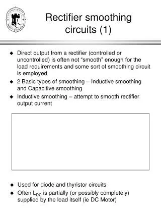
Diode Circuits or Uncontrolled Rectifier. Rectification: The process of converting the alternating voltages and currents to direct currents. The main disadvantages of half wave rectifier are: . High ripple factor, Low rectification efficiency, Low transformer utilization factor, and,

E N D
Diode Circuits or Uncontrolled Rectifier Rectification: The process of converting the alternating voltages and currents to direct currents
The main disadvantages of half wave rectifier are: High ripple factor, Low rectification efficiency, Low transformer utilization factor, and, DC saturation of transformer secondary winding.
Performance Parameters rectification effeciency form factor ripple factor
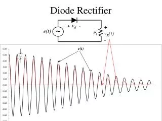
Example 1: The rectifier shown in Fig.2.1 has a pure resistive load of R Determine (a) The efficiency, (b) Form factor (c) Ripple factor (d) Peak inverse voltage (PIV) of diode D1. . (d) It is clear from Fig2.2 that the PIV is
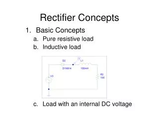
Half Wave Diode Rectifier With R-L Load Fig.2.3 Half Wave Diode Rectifier With R-L Load
Single-Phase Full-Wave Diode Rectifier Center-Tap Diode Rectifier
PIV of each diode = Example 3. The rectifier in Fig.2.8 has a purely resistive load of R Determine (a) The efficiency, (b) Form factor (c) Ripple factor (d) TUF (e) Peak inverse voltage (PIV) of diode D1 and(f) Crest factor of transformer secondary current.
Single-Phase Full Bridge Diode Rectifier With Resistive Load
Example 4 single-phase diode bridge rectfier has a purely resistive load of R=15 ohms and, VS=300 sin 314 t and unity transformer ratio. Determine (a) The efficiency, (b) Form factor, (c) Ripple factor, (d) The peak inverse voltage, (PIV) of each diode, , and, (e) Input power factor. The PIV=300V Input power factor =
Full Bridge Single-phase Diode Rectifier with DC Load Current
Example 5 solve Example 4 if the load is 30 A pure DC Input Power factor=
Effect Of LS On Current Commutation Of Single-Phase Diode Bridge Rectifier.
Example 6Single phase diode bridge rectifier connected to 11 kV, 50 Hz, source inductance Ls=5mH supply to feed 200 A pure DC load, find: (i) Average DC output voltage, (ii) Power factor. And (iii) Determine the THD of the utility line current.
ThePIV of the diodes is Example 7 The rectifier in Fig.2.21 is operated from 460 V 50 Hz supply at secondary side and the load resistance is R=20. If the source inductance is negligible, determine (a) Rectification efficiency, (b) Form factor (c) Ripple factor (d) Peak inverse voltage (PIV) of each diode.
The PIV= Vm=650.54V
Three-Phase Half Wave Rectifier With DC Load Current and zero source induct New axis
Example 8 Solve example 7 if the load current is 100 A pure DC The PIV= Vm=650.54V
Example 10 The rectifier shown in Fig.2.30 is operated from 460 V 50 Hz supply and the load resistance is R=20ohms. If the source inductance is negligible, determine (a) The efficiency, (b) Form factor (c) Ripple factor (d) Peak inverse voltage (PIV) of each diode .
The PIV= Vm=650.54V
Example 11 Three phase diode bridge rectifier connected to tree phase 33kV, 50 Hz supply has 8 mH source inductance to feed 300A pure DC load current Find; Commutation time and commutation angle. DC output voltage. Power factor. Total harmonic distortion of line current.