Download

1 / 58
580 likes | 780 Views
Product Training. Remote Manageable Media Converter. By. Infitel Co.,Ltd. Theory. Fiber Optic Fundamental. Link Budget Calculation. FDF. 1. FDF. 1. Splice. Rx. Tx. 2. Tx. Rx. 1. 3. 1. 3. 3. 3. 1. 1. Fiber Link Diagram.

E N D
Product Training Remote Manageable Media Converter By Infitel Co.,Ltd
Fiber Optic Fundamental Link Budget Calculation FDF 1 FDF 1 Splice Rx Tx 2 Tx Rx 1 3 1 3 3 3 1 1 Fiber Link Diagram Total Fiber Link Loss = Connector Loss + Fiber Loss + Splice Loss System Gain = Tx_min - Rx_sensitivity 1 2 3
Fiber Optic Fundamental Link Budget Calculation Link Budget >= System Gain – (Total Fiber Link Loss + Save Margin) Total Fiber Link Loss = Connector Loss + Fiber Loss + Splice Loss Connector Loss ~ 0.75 dB/point Fiber Loss ~ 0.4 dB/km @1310 nm, ~ 0.25 dB/km @1550nm. Splice Loss ~ 0.15 dB/point Save Margin ~ 3dB
Ethernet Overview ความหมายของ LFP (Link Fault Pass-through) Link Fault Pass Through มักจะใช้สำหรับการแก้ปัญหาในการทำงานกับ Media Converter กล่าวคือเมื่อด้านหนึ่งของ Link เกิด Fail อีกด้านก็จะยังคงทำการส่งแพ็กเก็ตต่อไปและรอการตอบกลับที่จะไม่มีวันมาถึง ดังรูป
Ethernet Overview ความหมายของ LFP (Link Fault Pass-through) อุปกรณ์ Media Converter ที่สนับสนุน LFP จะมีการสั่งให้ Link Shutdown โดยทันทีและส่งการแจ้งเตือนไปยัง Link อีกด้านว่ามีการ fail เกิดขึ้น ทำให้ Application Software สามารถรับทราบสถานการณ์ที่เกิดขึ้นได้ดังรูป
สรุปลักษณะการทำงานของ Function LFP (link fault pass-through) หรือ Link loss forwarding ได้เป็นดังนี้ 1. เมื่ออุปกรณ์ด้านที่ต่ออยู่กับ UTP Port ของ Media Converter หรือ UTP Port ของ Media Converter เอง ไม่สามารถรับส่งข้อมูลกันได้อุปกรณ์ Media Converter ต้องส่งสัญญาณไปแจ้งให้อุปกรณ์ที่ต่ออยู่กับ UTP Port ของ Media Converter อีกด้านหนึ่งทราบและทำให้อุปกรณ์ที่ต่ออยู่กับ UTP Port ตัวนั้นทำการ Shutdown UTP Port ของตัวเอง (Port) อยู่ในสภาวะไม่ทำงาน) 2. กรณีสาย Fiber Optic หรือ Port Optic ที่ต่อระหว่าง Media Converter ทั้งสองตัวขาดหรือใช้งานไม่ได้อุปกรณ์ Media Converter ทั้งสองตัว ต้องส่งสัญญาณไปแจ้งให้อุปกรณ์ที่ต่ออยู่กับ UTP Port ของตัวเองทราบและทำให้อุปกรณ์ที่ต่ออยู่กับ Media Converter นั้นทำการ Shutdown UPT Port ของตัวเอง (Port อยู่ในสภาวะไม่ทำงาน)
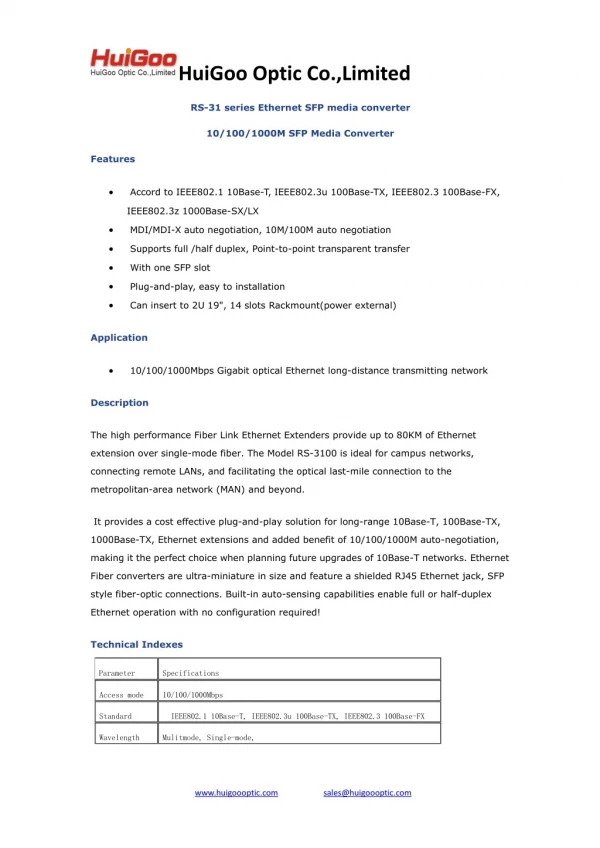
16-slot Chassis with SNMP Management Model : RC002-16 FEATURE : Slot Number :Up 16 slots for modular converters Redundant Power Supply :Two rear-loading, redundant, load-sharing, hot-swappable AC or DC or one AC and one DC power supplies Hot-wappable power supply :operate with single or dual AC or DC powersupplies. Each power supply supports a full rack of any combination of cards. The redundant power supply can be replaced without affecting system performance Hot-swappable modular converters : All cards are hot-swappable and can be replaced without interfering with the data transmission of other cards Network Management :The chassis can be managed by Raisecom network management platform Nview iEMS (graphic format), which allowing configuration management, diagnostics and loop activation, as well as monitoring and fault management Real-time configuration and monitoring : The management software enables the user to change the setup configuration, get real-time alerts on system status, activate diagnostics, and receive statistics on system functionality in a graphic format.
AC/DC Chassis Model : RC001-1WP FEATURE : Slot Number : 1 slot. Power Supply : wide range from AC to DC AC: 100V-240Vac, 0.5A, 50/60Hz DC: 48Vdc, 0.6A Efficient Heat dissipation : Optimal structure for efficient heat dissipation
Media converter Card Model : RC512-FE FEATURE : • Compatible with Raisecom RC001/RC002 series chassis • - RC552 has two working modes: Master and Slave. Central Office device works at Master • mode, and Customer Premise device at Slave mode. • Upstream and Downstream bandwidth allocation at 32Kbps increment • Fault pass - through • Auto MDI/MDIX
Media converter Card Model : RC512-FE
NView NNM Network Management System OVERVIEW It is designed to manage over devices from all Raisecom product lines on a uniform platform. With eight function components (topology management, resource management, configuration management, fault management, customer management, security management, performance management, log management)
NView NNM Network Management System Deployment This is the hardware configuration that we recommend when you deploy a NView NNM system. It guarantees the smooth operating of the system. The requirements on hardware configuration may increase as the capacity of the network under management increases.
NView NNM Network Management System Interface Layout & Topology Management •Topology List: shows the subnet nodes and device nodes in the whole network in a tree structure. •Network Topo: shows the topology of the network; the background and layout pattern are open to change. • The color of the node icon shows the highest-level alarm the corresponding subnet or device suffers. •Device auto-discovery & device offline status detection & link status detection function are supported •Subnet, device nodes and their shortcut nodes help the present of the relationship of different resources
NView NNM Network Management System Resource Management •Automatical & manual resource synchronization •Resource types under management include device, chassis, local card, remote device, and port. •Resource and customer information relation •Device & card type statistic, idle slot statistic, offline device statistic
NView NNM Network Management System Configuration Management • Chassis status monitoring • Local device/card, remote device and downlink devices of the remote device monitoring, configuration and reset • E1 & Ethernet port performance reporting • Loopback testing
NView NNM Network Management System Batch Configuration Task • Improves the efficiency of configuration when a configuration is required on a number of devices. • NView NNM provides three categories of batch tasks: software batch backup or upgrade, SNMP parameter setting, and switch related batch tasks.
NView NNM Network Management System Alarm Management • Five pre-defined alarm levels: critical, major, minor, warning, unknown, they're marked in different colors • Alarm counter on the toolbar counts the number of alarms of different alarm level in the network • Alarm event are kept in two lists: current alarm list and historical alarm list. Operations include "acknowledge" and "clear". • Alarm information includes infomration of related customer. Fault location becomes eaiser.
NView NNM Network Management System Alarm Management • The set-up of alarm filter rule helps users filter the displaying of alarms of a specified type and/or from a specified location. • Fault-removing experience management is available for quick fault-removing and effective alarm information analysis. • Alarm list auto-clearing service automatically clear useless alarm records according to customer's list
NView NNM Network Management System Customer Management • Customer list keeps information of all customers • The relationship between customer and resourses can be established on customer list, resourse management interface or device configuration interface. • Related customer information is recorded in alarm event information, which facilitates the location of the fault. • Quick customer information input and attaching for service modules in Raisecom network manageable chassis.
NView NNM Network Management System Security Management • Only authenticated users can enter the system and execute authorized operations in an authorized domain. • NView NNM defines three conceptions for security management “Domain”, “User Group” and “User”. • “User Access Control” function prevents users from logging in the system from unauthorized hosts by checking whether the host IP is on the user access control list. • NView NNM keeps “System Operation Log” and “Device Operation Log” to record a use's every key operation on the system and devices to assist administrator to trace the user's operation flow.
NView NNM Network Management System System Maintenance • Manually or scheduledly database backup • Database recover tool helps user to restore the database to a historical status. • NView NNM's self-contained debug information export function ensures that the information of all faults that occurs during system operating period will be exported to log files. Technical support engineers can locate and remove faults efficiently using these log files.
RC512-FE Optical Interface Specification
Connecting Media Converters to Ethernet Devices (UTP Interface) Using CAT-5 UTP (unshielded twisted pair) to connect the media converter, please note that the length of the UTP must not exceed 100 meters. 1. When the electrical interface Auto-Negotiation function enable, the MDI/MDIX (Crossover and Straight-through Auto-Negotiation) function will be enabled at the same time. The media converter can connect with other devices by either straight-through cable or crossover cable.
Connecting Media Converters to Ethernet Devices (UTP Interface) 2. When the electrical interface of the media converter is in force mode, the MDI/MDIX function will be disabled. In this circumstance, please following the connecting pattern in the table below:
RC512-FE The Front Panel of RC512-FE(B)
RC512-FE The Front Panel of RC512-FE(B)
RC512-FE Copper Interface Configuration DIP- switch SW20 SW20 is a 8-bit DIP-switch, including auto-negotiation enable / disable, speed 100M/10M, and full / half duplex mode. Function switch setting description
RC512-FE Copper Interface Configuration DIP- switch SW20 SW20 is a 8-bit DIP-switch, including auto-negotiation enable / disable, speed 100M/10M, and full / half duplex mode. Function switch setting description Note: 1. When switch SW20-1 is set to OFF, SW20-2 failure; 2. When RC512-FE-S (B), switch SW20-7 is Reserved.
RC512-FE Copper Interface Configuration DIP- switch SW20 SW20 is a 8-bit DIP-switch, including auto-negotiation enable / disable, speed 100M/10M, and full / half duplex mode. Function switch setting description Default setting: Note: SW20-7 of the default DIP must be set in accordance to the type of optical modules. When optical module is single-strand, SW 20-7 corresponding to SS15, SS25, and SS35 must be placed in OFF; SW20-7 corresponding to SS13, SS23, and SS34 must be placed ON.
NView NNM Network Management System RC002 EMS Overview RC002 EMS adopts GUI device management interface, enables users to manage the device through a management interface identical to the outline of the device, reflects the factual status of the device,and provides excellent device monitoring and maintenance function. At most 15 service modules can be inserted and managed in a RC002 chassis and users can manage 4 sets of chassis by one NE (network element). Installing the NView NNM platform and RC002 EMS, users can monitor and control devices like media converters, protocol converters, PDH multiplexers, and etc. of various models.
Start up the server Double-click the shortcut button on the desktop to start up the server. After the startup, NView NNM server will operate as a background service process. An icon will appear on the system tray. Periodical flash of the icon indicates that the server is operating normally, while no flash indicates the operating is stopped. Start up the server
Start Start up the client Double-click the “Client” shortcut on the desktop to start up the client when the server is operating. user name = administrator” password = “raisecom” Client logon interface
Close down the system Quit the client To close down the client, please click [System\Exit] on the system menu. A confirm box will pop up Client exit dialog box
Close down the system Close down the server To close down the server, please double-click the “Server-Stop” shortcut icon. A “Stop Server” dialog box will pop up. Confirm box for stopping the server
Launch the view of chassis NView NMS Window
Network topology list The topology list “Network Topo” on the left of the main view is composed of NE nodes including NE node and chassis node. Remote cards are connected to chassis. Users can launch multiform configuration interfaces and execute various services related commands through the topology list.
Customer information management Service Module Management Select a service module on the chassis panel and click [Config. Module] on the “Quick Start” pane or right-click the module on the chassis panel view and click [Config. Module] on the right-click menu, a module service configuration interface will open up. Switch to the “Customer Info.” page, users can view and modify the binding customers’ information of the selected service module “Customer Info.” page for a service module
Project information management Service Module Management Select a service module on the chassis panel view and click [Config. Module] on the “Quick Start” pane, or right-click on the module on the chassis view and click [Config. Module] on the right-click menu, the module service configuration interface for the selected module will open up. Switch to the “Project Info.” Page, users can view and modify the project information of the selected service module
Service Module Management Service configuration Select a service module on the chassis panel view and click [Config. Module] on the “Quick Start” pane, or right-click on the module on the chassis view and click [Config. Module] on the right-click menu, the service configuration interface for the selected module will open up. Switch to the “Card Info.”
Service Module Management Send reset command Select a service module on the chassis panel view and click [Reset Module] on the “Quick Start” pane, or right-click [Reset Module] on the right-click menu of the selected module The menu item for resetting a module
Service Module Management Performance monitoring and controlling Select a service module on the chassis panel view and click [Performance Stat.] on the “Quick Start” panel, or right-click on the module and click [Performance Stat.] on the right-click menu of the selected module the “Performance Stat.” window for the selected module will pop up Open the “Performance Stat.” window for a module through the chassis view
Service Module Management Performance monitoring and controlling Select a service module on the chassis panel view and click [Performance Stat.] on the “Quick Start” panel, or right-click on the module and click [Performance Stat.] on the right-click menu of the selected module the “Performance Stat.” window for the selected module will pop up “Performance Stat.” window
Operation and Maintenance Chassis temperature Click a chassis node on the topology list on the left of the main interface (Network Topo), the temperature information of the chassis will be displayed Chassis temperature information
Operation and Maintenance Device system information Click [System/System Information] in main menu of any chassis view on a NE, the “System Information” window will be open. Information like Contact, Name, Location, etc. can beconfigured “System Information” window
Operation and Maintenance Save current configuration Click [System/Save Current Config] in main menu of any chassis view on a NE and the “Confirm” dialog box will prompt whether save current configuration to flash The confirm box for “Save Current Config” Operation Progress bar for the “Save Current Config” Operation