Download
1 / 18
190 likes | 210 Views
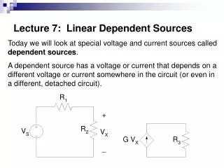
Circuit w/ Dependent Source Example. Find i 2 , i 1 and i o. +. . Using Equivalent Resistances. Simplify a circuit before applying KCL and/or KVL:. Example : Find I. I. R 1. R 1 = R 2 = 3 k W R 3 = 6 k W. R 3. R 2. 7 V. R 4. R 4 = R 5 = 5 k W R 6 = 10 k W. R 6. R 5.

E N D
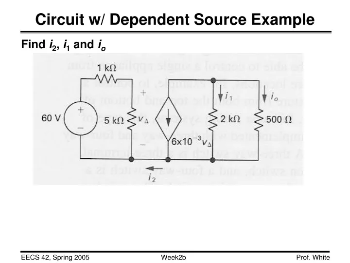
Circuit w/ Dependent Source Example Find i2, i1 and io
+ Using Equivalent Resistances Simplify a circuit before applying KCL and/or KVL: Example: Find I I R1 R1 = R2 = 3 kW R3 = 6 kW R3 R2 7 V R4 R4 = R5 = 5 kW R6 = 10 kW R6 R5
The Wheatstone Bridge • Circuit used to precisely measure resistances in the range from 1 W to 1 MW, with ±0.1% accuracy • R1and R2 are resistors with known values • R3 is a variable resistor (typically 1 to 11,000W) • Rx is the resistor whose value is to be measured battery R1 R2 + V – current detector R3 Rx variable resistor
Finding the value of Rx • Adjust R3 until there is no current in the detector Then, R2 R1 Rx = R3 • Derivation: • i1 = i3 and i2 = ix • i3R3 = ixRx and i1R1 = i2R2 • i1R3 = i2Rx KCL => KVL => R1 R2 i1 i2 + V – i3 ix R3 Rx R3 R1 Rx R2 = Typically, R2 / R1 can be varied from 0.001 to 1000 in decimal steps
R2 R1 R3 V R5 R4 + Identifying Series and Parallel Combinations Some circuits must be analyzed (not amenable to simple inspection) Special cases: R3 = 0 OR R3 =
Resistive Circuits: Summary • Equivalent resistance of kresistorsin series: Req = SRi = R1 + R2 + ••• + Rk • Equivalent resistance of k resistorsin parallel: • Voltage divided between 2 series resistors: • Current divided between 2 parallel resistors: k i=1 1 Req 1 Ri 1 Rk 1 R1 1 R2 k = S = + + ••• + i=1 R1 R1 + R2 v1 = vs R2 R1 + R2 i1 = is
Circuit Analysis Methods … • Given: a circuit with voltage and/of current sources, and components • (Rs, Cs, Ls, diodes, transistors, etc.) connected by wires • Task: find all the voltages and currents of interest • Approaches: • Use Ohm’s Law, KCL and KVL piecemeal • Nodal analysis – node voltages are the unknowns • Mesh (loop) analysis – mesh currents are the unknowns • Superposition (linear circuits) – work with only one voltage or current source at a time) and use #1, #2 or #3 • Computer simulation of circuit behavior
Node-Voltage Circuit Analysis Method • Choose a reference node (“ground”) Look for the one with the most connections! • Define unknown node voltages those which are not fixed by voltage sources • Write KCL at each unknown node, expressing current in terms of the node voltages (using the I-V relationships of branch elements) Special cases: floating voltage sources • Solve the set of independent equations N equations for N unknown node voltages
R1 R 3 + IS V1 R R - 2 4 Nodal Analysis: Example #1 • Choose a reference node. • Define the node voltages (except reference node and the one set by the voltage source). • Apply KCL at the nodes with unknown voltage. • Solve for unknown node voltages.
R 1 R 5 R I 3 1 V V R R 2 1 2 4 Nodal Analysis: Example #2 Va
V V LL V a b - + I R I R 1 2 2 4 Nodal Analysis w/ “Floating Voltage Source” A “floating” voltage source is one for which neither side is connected to the reference node, e.g. VLL in the circuit below: Problem: We cannot write KCL at nodes a or b because there is no way to express the current through the voltage source in terms of Va-Vb. Solution: Define a “supernode” – that chunk of the circuit containing nodes a and b. Express KCL for this supernode. Incorporate voltage source constraint into KCL equation.
Nodal Analysis: Example #3 supernode V V LL V a b - + I R I R 1 2 2 4 Eq’n 1: KCL at supernode Substitute property of voltage source:
Node-Voltage Method and Dependent Sources • If a circuit contains dependent sources, what to do? Example: iD 20 W 10 W 200 W – + 2.4 A 80 V – + 5iD
Node-Voltage Method and Dependent Sources • Dependent current source: treat as independent current source in organizing and writing node eqns, but include (substitute) constraining dependency in terms of defined node voltages. • Dependent voltage source: treat as independent voltage source in organizing and writing node eqns, but include (substitute) constraining dependency in terms of defined node voltages.
iD 20 W 10 W – + 200 W 2.4 A 80 V – + 5iD Example: