Download
1 / 24
250 likes | 268 Views
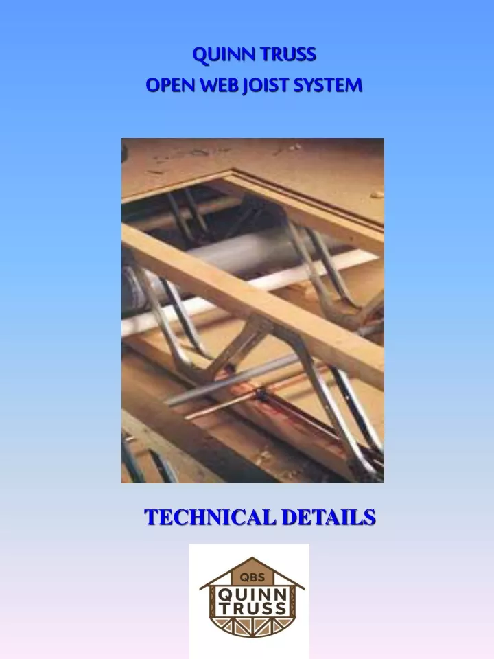
QUINN TRUSS OPEN WEB JOIST SYSTEM. TECHNICAL DETAILS. Finished beam depths. Web dimensions. PSD01 - L70 Hanger. Simpson L70 angles as specified by design. Simpson LBV hanger. Bottom member of posi beam to be notched over bottom flange of hanger. PSD02 - Bottom chord fixing to timber frame.

E N D
QUINN TRUSSOPEN WEB JOIST SYSTEM TECHNICAL DETAILS
PSD01 - L70 Hanger Simpson L70 angles as specified by design Simpson LBV hanger Bottom member of posi beam to be notched over bottom flange of hanger
PSD02 - Bottom chord fixing to timber frame 47x97 Top chord restraint fixed between beams
PSD03 - Top chord fixing to timber frame 47x97 Packing pieces Ring beam (size to suit) 6 mm gap 47x47 Continuous plasterboard noggin
PSD04 - Masonry hanger detail 47x97 Top chord restraint fixed between beams Minimum bearing determined by design (choose correct hanger for load, bearing width and coursework level of hanger bearing flange).
PSD05 - Masonry hanger detail(with continuous ledger) Continuous 47x97 ledger.Top chord of beam fixed to ledger Minimum bearing determined by design (choose correct hanger for load, bearing width and coursework level of bearing flange
PSD06 - Bottom chord built into masonry Blockwork to continue between beams to provide restraint
PSD07 - Top chord built into masonry Continuous 47x97 ledger fixed to wall Max 6mm gap
PSD08 - Top chord fixing to steel Wallplate fixed to top of steel 47x97 Noggins between top chords Timber pack fixed to beam (size ti suit) Max 6mm gap
PSD09 - Internal bearing on bottom chord 47x97 top chord restraint fixed between beams
PSD10 - Non load bearing partition parallel to beams Wall panels skew nailed through onto noggins with a min of 2 no 3.35 dia galvanised wire nails (length to suit). Simpson Z35N clips 38x97 C16 (min) noggins at max 600mm centres
PSD11 - Maximum duct sizes INSERT LARGE SERVICES THROUGH JOISTS BEFORE FIXING JOISTS. IT MAY NOT BE POSSIBLE AFTER JOISTS HAVE BEEN FIXED DOWN.
PSD12 - Edge closure detail 35mm Prefabricated edge closure pre faced with plywood with 20mm lap at the top edge Edge closure to be supplied to site as 4.8m long lengths and cut on site as required
PSD13 - Wide stair opening Simpson L70 angles as specified by design Simpson LBV hangers Bottom member of posi to be notched over bottom flange of hanger
PSD14 - Narrow stair opening Simpson L70 angles as specified by design Simpson LBV hanger Trimmer to be notched over bottom flange of hanger Trimmer depth to be adjusted on site to suit
PSD15 - Narrow stair opening Simpson L70 angles as specified by design Simpson LBV hanger Trimmer to be notched over bottom flange of hanger Trimmer depth to be adjusted on site to suit
PSD16 - Narrow stair opening Beam (depth to suit) Slotted through girders Simpson L70 angles as specified by design Packing piece to pick up ceiling
PSD17 - Strongback Detail Fix at a maximum of 4.0 metre centres 35x72 (min) blocks twice nailed to top and bottom members and twice nailed to brace using 3.35x90mm long galvanised wire nails Position strongbacks either tight to the underside of top chord (shown), or alternatively tight to topside of bottom chord INSTERT STRONGBACK THROUGH JOISTS BEFORE FIXING JOISTS. IT CANNOT BE INSTALLED AFTER JOISTS HAVE BEEN FIXED DOWN
PSD18 - Strongback Detail (with built in verticals) Fix at a maximum of 4.0 metre centres Position strongbacks either tight to the underside of top chord (shown), or alternatively tight to topside of bottom chord INSTERT STRONGBACK THROUGH JOISTS BEFORE FIXING JOISTS. IT CANNOT BE INSTALLED AFTER JOISTS HAVE BEEN FIXED DOWN
PSD19 - Strongback Bridging Bridging joists to overlap by at least 1 joist spacing and not less than 600mm
PSD20 - Strongback Splice Splice plate to be same section size as strongback Timber splice plate fixed to strongback with 10 nails each side of splice.
PSD21 - Horizontal restraint detail 35x97 timber twice nailed to bottom chord of each joist Strap to be fixed with a minimum of four fixings of which one is to be over the third joist