Download
1 / 24
240 likes | 244 Views
This paper presents the status of activities for the development of remote handling techniques for the maintenance of the IFMIF target assembly system. The European and Japanese target assembly concepts, refurbishment processes, and remote handling strategies are discussed.

E N D
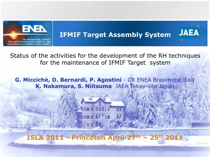
IFMIF Target Assembly System Status of the activities for the development of the RH techniques for the maintenance of IFMIF Target system G. Miccichè, D. Bernardi, P. Agostini - CR ENEA Brasimone Italy K. Nakamura, S. NiitsumaJAEA Tokay-siteJapan ISLA 2011 - Princeton April 27th – 29th 2011
Outline • Overview on the IFMIF targetassembly system • European TA concept • Japanese TA concept • The refurbishmentprocess of the TA • RH strategy • On-line refurbishment • Off-linerefurbishment • Remote Handling Equipment and tools • Conclusions
Overview of the IFMIF TA System The IFMIF Li Target Assembly: • deliveres the neutronirradiationfluxto Test Modules (TMs) fortestingfusion candidate materials up to 150 dpa ( 50 dpa/y) ofdamage rate; • islocated in side of the Test CellCavernthatis the mostcritical area of IFMIF facility(dose rate expected: 105 Sv/h on the BP at the shutdown ); Maintenanceof the TA requiresuseof sophisticated Remote Handlingtechnologies
Overview of the IFMIF TA System Requirements
The IFMIF Target Assembly RH MaintenanceRequirements Objective: perform all the RH activities within the intervention times to fulfil the stringent requirement of the plant availability. • Availability of Target Assembly: 95% of IFMIF plant availability 7600 hrs in scheduled operation time • Intervention Time for all scheduled tasks (Preventive maintenance) for IFMIF is : 720 hrs • Intervention time for all scheduled tasks for the refurbishment of the TA : 168 hrs • Two Target Assembly design conceptsare under investigation : • The EuropeanConcept(BayonetConcept -BC) • The JapaneseConcept(IntegralConcept - IC)
Bayonet TA Concept (EU Design) • The EU TA system isequippedwith a removableBackplate • ( BayonetConcept). It: • Simplifies the backplatereplacementoperation • Reduces the amountof material fordisposal • Improves the duty cycleof the plant • Allowstoperformitsreplacementoperationin-situ. • Sealingof the BP: Low delta seal HNV200 Helicoflexgasket Li Inlet Pipe Nozzle Beam Ducts Itisconnectedto the Li loop and with the beamductbymeansofQuickDisconnecting System (QDS) Selaingof the Flanges : Helicoflex HN 100 (TBC) Quench Tank
IntegratedTA Concept (JA Design) IntegratedTA (JA plan) is integrated with Back Plate and has several connections for replacement . • Dissimilar welding (off-site) • Welding by TIG welding or another • method at off-site • -Dissimilar materials : 316L/F82H F82H Integrated Target Assembly (integrated with Back Plate) F82H Beam Ducts 316L 316L • Lip-seal welding & cutting (on-site) • Liquid lithium flow channel • Welding & cutting by remote • handling because of on-site • -Similar materials : 316L • - Connection support by clamping Inlet Pipe Quench Tank Mechanical-seal ( Quick Disconnecting system) - Lithium vapor atmosphere - The lithium doesn't touch direct in the seal part Overview of IntegratedTA
Remote Handlingstrategy • Twopotentialapproaches: • On-line TA Refurbishment (only the EU target concept); • Off-line TA Refurbishment ( EU and JA concepts); • On line TA Refurbishment • Intervention time for the replacement of the BP bayonet concept is < 2 days • ( cleaning, inspection and test are not included) • Not all tasks can be performed ( nozzle exch. ) • Minimum space in front of the back plate is needed ( shift of 70÷100 mm the test modules) • Preferable to be implemented if a significant misalignment between the replacement times of the Backplate and the Test Modules will occur. Test Modules Target area Cables and pipes
Remote HandlingStrategy Off-line TA’s Refurbishment ( preventive maintenance) • Replacement of the TA was planned every (30 years CDR) (10 years PSAR); • Expected TA life time is still uncertain due to the erosion/corrosion of the nozzle that could be shorter than expected; • The refurbishment of the TA should be performed off-line in a hot cell • The Off-line strategyallowsto: • make the maintenance in muchsafer and relaxedconditions; • test all the assembledcomponents • improve the safetyof the system ( newgasketseachtime) • Thisstrategyrelies on the availabilityof a new target ( previuslyrefurbished) readytobeinstalled.
Integral target RH procedure moving image was prepared Target guide rail Target Assembly Target assembly Lifting up Start Target assembly Lifting end Target assembly Guide Free position ① ② ③
QuickDisconnecting system (QDS) • Objectives: • Design, qualification and validation of a new Quick disconnecting System (QDS) for RH; • Qualify the Helicoflex gasket : Li corrosion; vacuum and leak rate achievable , and other specific tests ( TBD with Garlock); • Advantages: • Easy and rapid to assemble and disassemble • Reduced number of bolting points • Compact size (reduction of size) • Good efficiency (limitation of torque) • usable in restricted area This system permitstoreplace the TA within the interventiontimeforeseenfor the BP exchange ( i.e < 2 days-cleaning and otheroperationsnotincluded) SharedR&DProgram ENEA- GarlockGmbH
QuickDisconnecting system (QDS) • The Design and R&Dactivities include the: • Selectionof the sealing system (one or twogaskets) • Li leak detection system • detachment system for the QDS in case offailure • System for the removalof the insulationfrom the flanges • Validationof the QDS willbeperformed in Garlock (France) and in ENEA Brasimone: • RH test (ENEA Facility) • test of the QDS in Li environment (ENEA Loop/GarlockFactory) Rigsfor test of the Gaskets Test of the QDS apparatus The QDS isdesignedaccordingto ASME or RCC-MRxcodes
RH procedures and Tooling Whateverapproacheswillbeselectedsuitableprocedures and toolshavetobedelelopedfor: Li cleaning process Inspection and test of the target Pre-heatingof the target at the start up of the loop ( thermal stress), BP and Target exchange Almostall the RH Validationtasksfor the EuropeanTarget, including the R&Dfor the QDS qualification, willbeperformed at CR ENEA at Brasimone (DRP Facility) in the next 2 years. JAEA isperforming the RH activitiesfor the IC. Simulation of Solid Lithium deposition
Cleaning Procedure A thincoatingoflithium (few µm) isexpected on the interface frame and on the connectingflangesaswell. The cleaning procedure hasalreadybeendeveloped and tested: CH3COOH+ H2O2 + CH3CH2OH [ratio (1:1:1)] A few
Cleaning Procedure • A NEW Cleaningtoolis under development. • MainFeatures are: • providedwith a belt system • virgintapealways in contactwith the area tobecleaned • integratedsprying system for the adductionof the cleaningsolution • low force system • modus horizontal • easy removalof the end effector ( requirement) Take up spool Delivery spool Telerobot (Genova -Italy) Gripper interface Belt conveyor
Bolting tool and Robotic Arm • ManipulatorArm System: • ( usedforalmostall the Refurbishmenttasks) • Sixdegreesoffreedom • Armpayload ( 200 Kg) • PositionalAccurancy ±0,5 mm • lifterintegrated (Payload 1,5 T) • Design of the ManipulatorArmwill start in June 2011. Manufacturing in late 2011. • BoltingTool • ( usedfor the backlate and target replacement ) • Controlled in angle and torque • Torquerange 3÷80 Nm • Accuracy 2% • A radhardversionofthistoolis under design
Concept of Remote Handling System Manipulator Subsystem Remote Handling System consists of: Manipulator Subsystem - Transporting Laser Subsystem to TTC vessel. - Setting Laser Subsystem to lip seal flange. Laser Subsystem - Clamping inlet pipe of TA. - Cutting & welding lip seal flange by fiber Laser. Manipulator Laser Subsystem
Outline of Laser Subsystem LaserSubsystem is transported by manipulator , installed near lip seal flange and cutting /welding operation is carried out by remote control. Inlet pipe (316L) power & gas supply cable Laser Head Cutting Position & Welding position Φ216.3 Manipulator Lip seal flange Li inlet piping Lip seal flange Laser Subsystem Integrated TA (F82H) Beam Ducts Φ330(min.) Clamping Portion to pipe Laser Head Welding Position Installation of Laser Subsystem
Status of LF05-JA Remote Handling LaserSubsystem has six axis which are driven by AC servo motor, reduction device, ballscrew and so on, therefore laser head position can be controlled precisely. This prototype was already fabricated in Mar. 2011. Laser Head θ X V Z Y W Pipe clamping Weight:127 Kg
Procedure ofLaser Subsystem Installation Manipulater Standby position Laser Sub System moving image was prepared Laser Sub System Installation position Laser Sub System Operating state Laser Sub System Setting ① ② ③
Status of LF05-JA Remote Handling • Mock-up test by prototype of Laser Subsystem • - Validation of Fiber Laser cut & re-welding by Laser Subsystem Work (simulating Li inlet pipe with lip seal) Test stand Prototype of Laser Subsystem
Conclusions • The maintenanceof the IFMIF TA system is a rathercomplexactivitywhichrequires a wide R&Dprogramfor the validationof the TA concepts, from the RH viewpoint, and of the RHEs and toolstobeused; • The RH experimentalactivities are progressingevenif the RH strategyhasnotfixedyet. Howeverthere are several common RH tasksthatcould help to take the finalchoice on the refurbishmentapproachestobeadopted. ( Qualificationof the QDS system and final design of the RH for Test Modulesforinstance) • There are stillseveral open points on the design of the RHEs and toolstobeused (notdescribed in the presentation): useofRad Hard technologyismandatory ; viewingsystemscapabletowithstandto the high dose rate expected in the test cell and in the otherfacilitiesaswell.
Acknowledgemnts Thanksforyourattention I wouldlikealsotothank the: Japanesecolleagues, Telerobot ( Genova)- Italy, GarlockGmBH–France, Tekva (Milano)–Italy ,(KarlsruheInstituteofTechnology)–Germany and UniversityofPalermo-Italy