Download
1 / 14
140 likes | 270 Views
88-B2-2F-54-1A-0F. 74-29-9C-E8-FF-55. E6-E9-00-17-BB-4B. 222.222.222.221. 1A-23-F9-CD-06-9B. 111.111.111.111. 222.222.222.222. 222.222.222.220. 111.111.111.110. R. 111.111.111.112. 49-BD-D2-C7-56-2A. CC-49-DE-D0-AB-7D. A. B. Addressing: routing to another LAN.

E N D
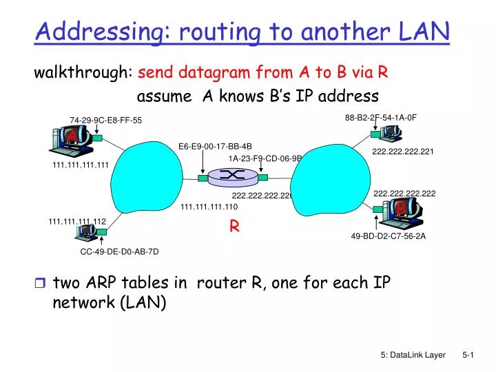
88-B2-2F-54-1A-0F 74-29-9C-E8-FF-55 E6-E9-00-17-BB-4B 222.222.222.221 1A-23-F9-CD-06-9B 111.111.111.111 222.222.222.222 222.222.222.220 111.111.111.110 R 111.111.111.112 49-BD-D2-C7-56-2A CC-49-DE-D0-AB-7D A B Addressing: routing to another LAN walkthrough: send datagram from A to B via R assume A knows B’s IP address • two ARP tables in router R, one for each IP network (LAN) 5: DataLink Layer
88-B2-2F-54-1A-0F 74-29-9C-E8-FF-55 E6-E9-00-17-BB-4B 222.222.222.221 1A-23-F9-CD-06-9B 111.111.111.111 222.222.222.222 222.222.222.220 B A 111.111.111.110 R 111.111.111.112 49-BD-D2-C7-56-2A CC-49-DE-D0-AB-7D This is a really important example – make sure you understand! • A creates IP datagram with source A, destination B • A uses ARP to get R’s MAC address for 111.111.111.110 • A creates link-layer frame with R's MAC address as dest, frame contains A-to-B IP datagram • A’s NIC sends frame • R’s NIC receives frame • R removes IP datagram from Ethernet frame, sees its destined to B • R uses ARP to get B’s MAC address • R creates frame containing A-to-B IP datagram sends to B 5: DataLink Layer
5.1 Introduction and services 5.2 Error detection and correction 5.3Multiple access protocols 5.4 Link-Layer Addressing 5.5 Ethernet 5.6 Link-layer switches 5.7 PPP 5.8 Link Virtualization: ATM and MPLS Link Layer 5: DataLink Layer
Ethernet “dominant” wired LAN technology: • cheap $20 for NIC • first widely used LAN technology • simpler, cheaper than token LANs and ATM • kept up with speed race: 10 Mbps – 10 Gbps Metcalfe’s Ethernet sketch 5: DataLink Layer
Star topology • bus topology popular through mid 90s • all nodes in same collision domain (can collide with each other) • today: star topology prevails • active switch in center • each “spoke” runs a (separate) Ethernet protocol (nodes do not collide with each other) switch bus: coaxial cable star 5: DataLink Layer
Ethernet Frame Structure Sending adapter encapsulates IP datagram (or other network layer protocol packet) in Ethernet frame Preamble: • 7 bytes with pattern 10101010 followed by one byte with pattern 10101011 • used to synchronize receiver, sender clock rates 5: DataLink Layer
Ethernet Frame Structure (more) • Addresses: 6 bytes • if adapter receives frame with matching destination address, or with broadcast address (eg ARP packet), it passes data in frame to network layer protocol • otherwise, adapter discards frame • Type: indicates higher layer protocol (mostly IP but others possible, e.g., Novell IPX, AppleTalk) • CRC: checked at receiver, if error is detected, frame is dropped 5: DataLink Layer
Ethernet: Unreliable, connectionless • connectionless: No handshaking between sending and receiving NICs • unreliable: receiving NIC doesn’t send acks or nacks to sending NIC • stream of datagrams passed to network layer can have gaps (missing datagrams) • gaps will be filled if app is using TCP • otherwise, app will see gaps • Ethernet’s MAC protocol: unslotted CSMA/CD 5: DataLink Layer
application transport network link physical fiber physical layer copper (twister pair) physical layer 802.3 Ethernet Standards: Link & Physical Layers • many different Ethernet standards • common MAC protocol and frame format • different speeds: 2 Mbps, 10 Mbps, 100 Mbps, 1Gbps, 10G bps • different physical layer media: fiber, cable MAC protocol and frame format 100BASE-T2 100BASE-FX 100BASE-TX 100BASE-BX 100BASE-SX 100BASE-T4 5: DataLink Layer
5.1 Introduction and services 5.2 Error detection and correction 5.3 Multiple access protocols 5.4 Link-layer Addressing 5.5 Ethernet 5.6 Link-layer switches 5.7 PPP 5.8 Link Virtualization: ATM, MPLS Link Layer 5: DataLink Layer
twisted pair hub Hubs … physical-layer (“dumb”) repeaters: • bits coming in one link go out all other links at same rate • all nodes connected to hub can collide with one another • no frame buffering • no CSMA/CD at hub: host NICs detect collisions 5: DataLink Layer
Switch • link-layer device: smarter than hubs, take active role • store, forward Ethernet frames • examine incoming frame’s MAC address, selectively forward frame to one-or-more outgoing links when frame is to be forwarded on segment, uses CSMA/CD to access segment • transparent • hosts are unaware of presence of switches • plug-and-play, self-learning • switches do not need to be configured 5: DataLink Layer
Switch: allows multiple simultaneous transmissions A • hosts have dedicated, direct connection to switch • switches buffer packets • Ethernet protocol used on each incoming link, but no collisions; full duplex • each link is its own collision domain • switching:A-to-A’ and B-to-B’ simultaneously, without collisions • not possible with dumb hub C’ B 1 2 3 6 4 5 C B’ A’ switch with six interfaces (1,2,3,4,5,6) 5: DataLink Layer
Switch Table A • Q: how does switch know that A’ reachable via interface 4, B’ reachable via interface 5? • A: each switch has a switch table, each entry: • (MAC address of host, interface to reach host, time stamp) • looks like a routing table! • Q: how are entries created, maintained in switch table? • something like a routing protocol? C’ B 1 2 3 6 4 5 C B’ A’ switch with six interfaces (1,2,3,4,5,6) 5: DataLink Layer