Download
1 / 67
740 likes | 841 Views
Electromagnetic Define and explain Faraday Law, Flemming Law, magnetic field, magnetik material, Magnetisation curve Define and explain magnetic equivalent circuit, electromagnetic induction, Sinusoidal excitation, Lenz’s law. Analyze and explain magnetic losses, eddy current, hysterisis.

E N D
Electromagnetic • Define and explain Faraday Law, Flemming Law, magnetic field, magnetik material, Magnetisation curve • Define and explain magnetic equivalent circuit, electromagnetic induction, Sinusoidal excitation, Lenz’s law. • Analyze and explain magnetic losses, eddy current, hysterisis
CHAPTER 11 MAGNETIC FIELDS
11.2 Magnetic Fields • In the region surrounding a permanent magnet there exists a magnetic field, which can be represented by magnetic flux lines similar to electric flux lines. • Magnetic flux lines differ from electric flux lines in that they don’t have an origin or termination point. • Magnetic flux lines radiate from the north pole to the south pole through the magnetic bar.
11.2 Magnetic Fields Flux distribution for a permanent magnet
11.2 Magnetic Fields • Continuous magnetic flux lines will strive to occupy as small an area as possible. • The strength of a magnetic field in a given region is directly related to the density of flux lines in that region. • If unlike poles of two permanent magnets are brought together the magnets will attract, and the flux distribution will be as shown below.
11.2 Magnetic Fields Flux distribution for two adjacent, opposite poles
11.2 Magnetic Fields • If like poles are brought together, the magnets will repel, and the flux distribution will be as shown.
11.2 Magnetic Fields • If a nonmagnetic material, such as glass or copper, is placed in the flux paths surrounding a permanent magnet, there will be an almost unnoticeable change in the flux distribution. • If a nonmagnetic material, such as glass or copper, is placed in the flux paths surrounding a permanent magnet, there will be an almost unnoticeable change in the flux distribution.
11.2 Magnetic Fields • This principle is put to use in the shielding of sensitive electrical elements and instruments that can be affected by stray magnetic fields.
11.2 Magnetic Fields • A current-carrying conductor develops magnetic fields in the form of concentric circle around it.
11.2 Magnetic Fields • If the coil is wound in a single-turn coil, the resulting flux flows in a common direction through the centre of the coil.
11.2 Magnetic Fields • A coil of more than one turn produces a magnetic field that exists in a continuous path through and around the coil.
11.2 Magnetic Fields • The flux distribution around the coil is quite similar to the permanent magnet. • The flux lines leaving the coil from the left and entering to the right simulate a north and a south pole. • The concentration of flux lines in a coil is less than that of a permanent magnet.
11.2 Magnetic Fields • The field concentration (or field strength) may be increased effectively by placing a core made of magnetic materials (e.g. iron, steel, cobalt) within the coil – electromagnet.
11.2 Magnetic Fields • The field strength of an electromagnet can be varied by varying one of the component values (i.e. currents, turns, material of the core etc.)
11.2 Magnetic Fields • The direction of the magnetic flux lines can be found by placing the thumb of the right hand in the direction of conventional current flow and noting the direction of the fingers (commonly called the right hand rule).
11.2 Magnetic Fields Flux and Flux Density • In the SI system of units, magnetic flux is measured in webers (Wb) and is represented using the symbol .
Wilhelm Eduard Weber (1804 – 1891)Prof. of Physics, University of Göttingen
11.2 Magnetic Fields • The number of flux lines per unit area is called flux density (B). Flux density is measured in teslas (T). • Its magnitude is determined by the following equation: 1 tesla = 1 T = 1 Wb/m2
Nikola Tesla (1856 – 1943)Electrical Engineer and Inventor Recipient of the Edison Medal in 1917.
11.2 Magnetic Fields • The flux density of an electromagnet is directly related to: • the number of turns of • the current through • the coil • The product is the magnetomotive force:
11.2 Magnetic Fields Permeability • Another factor affecting the field strength is the type of core used. • If cores of different materials with the same physical dimensions are used in the electromagnet, the strength of the magnet will vary in accordance with the core used. • The variation in strength is due to the number of flux lines passing through the core.
11.2 Magnetic Fields • Magnetic material is material in which flux lines can readily be created and is said to have high permeability. • Permeability () is a measure of the ease with which magnetic flux lines can be established in the material.
11.2 Magnetic Fields • Permeability of free space 0 (vacuum) is • Materials that have permeability slightly less than that of free space are said to be diamagnetic and those with permeability slightly greater than that of free space are said to be paramagnetic.
11.2 Magnetic Fields • Magnetic materials, such as iron, nickel, steel and alloys of these materials, have permeability hundreds and even thousands of times that of free space and are referred to as ferromagnetic. • The ratio of the permeability of a material to that of free space is called relative permeability:
11.2 Magnetic Fields • In general for ferromagnetic materials, • For nonmagnetic materials, • Relative permeability is a function of operating conditions.
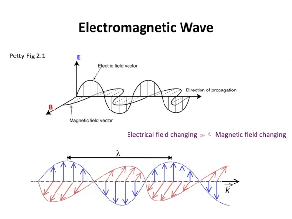
11.4 Induced Voltage • If a conductor is moved through a magnetic field so that it cuts magnetic lines of flux, a voltage will be induced across the conductor.
11.4 Induced Voltage • The magnitude of the induced voltage is directly related to the speed of movement (i.e. at which the flux is cut). • Moving the conductor in parallel with the flux lines will result in zero volt of induced voltage.
11.4 Induced Voltage • If a coil of conductor instead of a straight conductor is used, the resultant induced voltage will be greater Faraday’s law of electromagnetic induction • If a coil of N turns is placed in the region of the changing flux, as in the figure below, a voltage will be induced across the coil as determined by Faraday’s Law.
11.4 Induced Voltage • Changing flux also occurs in a coil carrying a variable current. • Similar voltage will be induced, the direction of which can be determined by Lenz’s Law.
11.4 Induced Voltage Lenz’s law • An induced effect is always such as to oppose the cause that produced it. • The magnitude of the induced voltage is given by: • L is known as inductance of the coil and is measure in henries (H)
CHAPTER 12 MAGNETIC CIRCUITS
12.1 Introduction • Magnetism is an integral part of almost every electrical device used today in industry, research, or the home. • Generators, motors, transformers, circuit breakers, televisions, computers, tape recorders and telephones all employ magnetic effects to perform a variety of important tasks.
12.3 Reluctance • The resistance of a material to the flow of charge (current) is determined for electric circuits by the equation • The reluctance of a material to the setting up of magnetic flux lines in a material is determined by the following equation
12.4 Ohm’s Law for Magnetic Circuits • For magnetic circuits, the effect is the flux . • The cause is the magnetomotive force (mmf) F,which is the external force (or “pressure”) required to set up the magnetic flux lines within the magnetic material. • The opposition to the setting up of the flux is the reluctance .
12.4 Ohm’s Law for Magnetic Circuits • Substituting: • The magnetomotive force is proportional to the product of the number of turns around the core (in which the flux is to be established) and the current through the turns of wire
12.4 Ohm’s Law for Magnetic Circuits • An increase in the number of turns of the current through the wire, results in an increased “pressure” on the system to establish the flux lines through the core.
12.5 Magnetizing Force • The magnetomotive force per unit length is called the magnetizing force (H). • Magnetizing force is independent of the type of core material. • Magnetizing force is determined solely by the number of turns, the current and the length of the core.
12.5 Magnetizing Force • Substituting:
12.5 Magnetizing Force • The flux density and the magnetizing force are related by the equation:
12.6 Hysteresis • Hysteresis – The lagging effect between the flux density of a material and the magnetizing force applied. • The curve of the flux density (B) versus the magnetic force (H) is of particular interest to engineers.
12.6 Hysteresis Series magnetic circuit used to define the hysteresis curve.
12.6 Hysteresis • The entire curve (shaded) is called the hysteresis curve. • The flux density B lagged behind the magnetizing force H during the entire plotting of the curve. When H was zero at c, B was not zero but had only begun to decline. Long after H had passed through zero and had equaled to –Hd did the flux density B finally become equal to zero
12.6 Hysteresis Hysteresis curve.
12.6 Hysteresis • If the entire cycle is repeated, the curve obtained for the same core will be determined by the maximum H applied.
12.6 Hysteresis Normal magnetization curve for three ferromagnetic materials.
12.6 Hysteresis Expanded view for the low magnetizing force region.