Download
1 / 165
1.65k likes | 1.67k Views
Power Amplifiers. Chapter 01, 02. Functional blocks of an amplifier. All power amplifiers have: 1.A Power supply 2.A n input stage 3.A n output stage. 1.Power Supply.

E N D
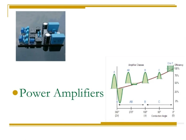
Power Amplifiers Chapter 01, 02
Functional blocks of an amplifier • All power amplifiers have: 1.A Power supply 2.An input stage 3.An output stage
1.Power Supply • The primary purpose of a power supply in a power amplifier is to take the 120 V AC power from the outlet and convert it to a DC voltage. • The very best of amplifiers have two totally independent power supplies, one for each channel (they do share a common AC power cord though).
2. Input Stage • The general purpose of the input stage of a power amplifier (sometimes called the "front end") is to receive and prepare the input signals for "amplification" by the output stage. • Two types: 1.Balanced Input 2.Single Ended Input
2. Input Stage • Balanced inputs are much preferred over single ended inputs when interconnection cables are long and/or subject to noisy electrical environments because they provide very good noise rejection. • The input stage also contains things like input level controls.
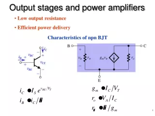
3.Output Stage • The portion which actually converts the weak input signal into a much more powerful "replica" which is capable of driving high power to a speaker. • This portion of the amplifier typically uses a number of "power transistors" (or MOSFETs) and is also responsible for generating the most heat in the unit. • The output stage of an amplifier interfaces to the speakers.
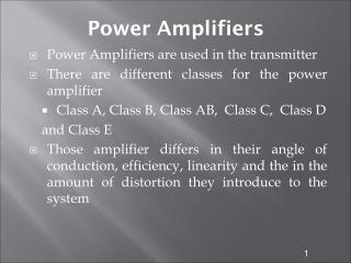
Amplifier Classes • The Class of an amplifier refers to the design of the circuitry within the amp. • For audio amplifiers, the Class of amp refers to the output stage of the amp.
Classes Collector current waveforms for transistors operating in (a) class A, (b) class B, (c) class AB, and (d) class C amplifier stages.
Class-A: Output device(s) conduct through 360 degrees of input cycle(never switch off) - A single output device is possible. The device conducts for the entire waveform in Figure 1 • Class-B: Output devices conduct for 180 degrees (1/2 of input cycle) - for audio, two output devices in "push-pull" must be used (see Class-AB) • Class-AB: Halfway (or partway) between the above two examples (181 to 200 degrees typical) - also requires push-pull operation for audio. The conduction for each output device is shown in Figure 1.
Class-C: Output device(s) conduct for less than 180 degrees (100 to 150 degrees typical) - Radio Frequencies only - cannot be used for audio! This is the sound heard when one of the output devices goes open circuit in an audio amp! See Figure 1, showing the time the output device conducts
Class A Output Stage • Class A output stage is a simple linear current amplifier. • It is also very inefficient, typical maximum efficiency between 10 and 20 %. • Only suitable for low power applications. • High power requires much better efficiency.
Basic class A amplifier operation. Output is shown 180∞ out of phase with the input (inverted).
Maximum class A output occurs when the Q-point is centered on the ac load line.
FIGURE 9-30 Class A power amplifier with correct output voltage swing.
Why is class A so inefficient ? • Single transistor can only conduct in one direction. • D.C. bias current is needed to cope with negative going signals. • 75 % (or more) of the supplied power is dissipated by d.c. • Solution : eliminate the bias current.
Class A • Class A amplifiers have very low distortion (lowest distortion occurs when the volume is low) • They are very inefficient and are rarely used for high power designs. • The distortion is low because the transistors in the amp are biased such that they are half "on" when the amp is idling
Class A • As a result of being half on at idle, a lot of power is dissipated in the devices even when the amp has no music playing! • Class A amps are often used for "signal" level circuits (where power requirements are small) because they maintain low distortion.
Class-A Benefits • The first is circuit simplicity. • The signal is subjected to comparatively little amplification, resulting in an open loop gain which is generally fairly low. • This means that very little overall feedback is used, so stability and phase should be excellent over the audio frequencies. • Do not require any frequency compensation.
Class-A Benefits • No cross over distortion • No switching distortion • Lower harmonic distortion in the voltage amplifier • Lower harmonic distortion in the current amplifier • No signal dependent distortion from the power supply • Constant and low output impedance • Simpler design
Illustration of crossover distortion in a class B push-pull amplifier. The transistors conduct only during the portions of the input indicated by the shaded areas.
Transformer coupled push-pull amplifiers. Q1 conducts during the positive half-cycle; Q2 conducts during the negative half-cycle. The two halves are combined by the output transformer.
Biasing the push-pull amplifier to eliminate crossover distortion.
Class B Output Stage • Q1 and Q2 form two unbiased emitter followers • Q1 only conducts when the input is positive • Q2 only conducts when the input is negative • Conduction angle is, therefore, 180° • When the input is zero, neither conducts • i.e. the quiescent power dissipation is zero
Class B Current Waveforms Iout time IC1 time IC2 time
IC1 A/RL 0 p 2p Phase, q Class B Efficiency Average power drawn from the positive supply: A sin(q)
Load power: Efficiency: By symmetry, power drawn from +ve and –ve supplies will be the same. Total power, therefore:
Power Dissipation To select appropriate output transistors, the maximum power dissipation must be calculated. Just need to find the maximum value of PD to select transistors/heatsinks
Efficiency / Power Dissipation • Peak efficiency of the class B output stage is 78.5 %, much higher than class A. • Unlike class A, power dissipation varies with output amplitude. • Remember, there are two output devices so the power dissipation is shared between them.
Cross-Over Distortion • A small base-emitter voltage is needed to turn on a transistor • Q1 actually only conducts when vin > 0.7 V • Q2 actually only conducts when vin < -0.7 V • When 0.7 > vin > -0.7, nothing conducts and the output is zero. • i.e. the input-output relationship is not at all linear.
Class B • A class B output stage can be far more efficient than a class A stage (78.5 % maximum efficiency compared with 25 %). • It also requires twice as many output transistors… • …and it isn’t very linear; cross-over distortion can be significant.
Class B • Class B amplifiers are used in low cost designs or designs where sound quality is not that important. • Class B amplifiers are significantly more efficient than class A amps. • They suffer from bad distortion when the signal level is low (the distortion in this region of operation is called "crossover distortion").