Download
1 / 28
280 likes | 619 Views
Media Advances: High-Fidelity Audio from Integrated Audio Components. Hakon Strande Program Manager WMDG hakons @ microsoft.com Microsoft Corporation. David Roach Audio Evangelist droach@sigmatel.com. Session Outline. In Search of Better Audio Why Terminology Attributes of Good Audio

E N D
Media Advances:High-Fidelity Audio from Integrated Audio Components Hakon Strande Program ManagerWMDGhakons @ microsoft.com Microsoft Corporation David Roach Audio Evangelist droach@sigmatel.com
Session Outline • In Search of Better Audio • Why • Terminology • Attributes of Good Audio • Audio is Part of the System • Common Complaints • Considerations • Testing • Resources
Why Focus on Fidelity From Integrated Audio? • Much can be gained with minimal effort • Design board with audio in mind • Our motivation for providing these guidelines • 95% of PC audio solutions are integrated • Microsoft would like the Windows PC to achieve parity with Consumer Electronics fidelity • Microsoft Universal Audio Architecture initiative • Standardizing external and integrated audio around established technology specifications • Integrated audio UAA compliant solution is Intel High Definition Audio • Has great potential if device and board implementation is done with fidelity in mind
Terminology • In order to understand and communicate about audio, consistent terminology must be used • Volt • Decibel (dB) • Hertz • Octave • Frequency Response • Signal To Noise Ratio (SNR) • Total Harmonic Distortion plus Noise (THD+N)
What Is A Volt? • The expected line input and output level of a PC is 1 Volt RMS for PCs using 5 Volts DC for the analog audio power supply (AVdd) • PCs using 3.3V power supplies for AVdd are expected to put out at least 0.707 Volts RMS • RMS stands for “Root Mean Square”, and is a method for measuring voltages that corresponds more closely to the perception of the human ear • 1 Volt RMS: • Is the same as 1.414 Volts Peak • Which is the same as 2.828 Volts Peak-to-Peak
What is a Decibel or dB? • A Bel was named after Alexander Graham Bell, the inventor of the telephone; It is a unit which defines a doubling of loudness • A decibel is 1/10th of a Bel • A decibel is commonly expressed as a ratio of two values • 0 dBV is referenced to 1 Volt RMS; Each doubling or halving of voltage is approximately 6 dB • dB FS (Full Scale) is a measurement of digital signals relative to the maximum possible value • 0 dB FS = maximum value possible, all other levels are expressed as minus • The average human ear has a dynamic range of over 10 Bels, or 100 dB • Voltage is linear scale, dB is log scale • A range of 60 dB is a ratio of a thousand to one • A range of 120 dB is a ratio of a million to one • 3 dB is the smallest volume step that a typical untrained listener can easily discern; Trained listeners can identify smaller steps
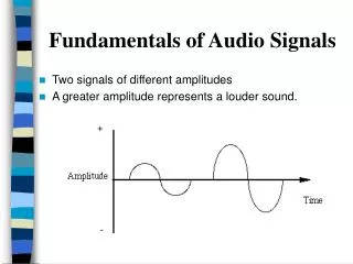
What Are Hertz? • Hertz is an measure of frequency expressed in cycles per second • A pure sine wave has a tone at only one frequency • A complex waveform will contain combinations of many different frequencies at any one time • The typical range of human hearing is 20 Hertz (Bass) to 20 kiloHertz (Treble)
What Is An Octave? • An octave is a doubling of frequency • The average human ear has a frequency response of over 10 octaves • Hertz is linear scale, octave is log scale • 10-octave ISO (International Standards Organization) center frequencies • 31.25 Hz • 62.5 Hz • 125 Hz • 250 Hz • 500 Hz • 1000 Hz • 2000 Hz • 4000 Hz • 8000 Hz • 16000 Hz • Note that the ear has log response for both frequency (octaves) and volume (db), but our test equipment normally uses the linear scales such as Volts and Hertz
Attributes of Good Audio • High Dynamic Range (DR) • Can accommodate both soft and loud signals • Adequate Headroom • Ability to reproduce peaks without distortion • High Signal to Noise Ratio, or SNR • Freedom from noise • Low Distortion, or THD+N • Freedom from distortion • Full-range frequency response • Match the range of human hearing • Low channel-to-channel crosstalk • Minimize leakage between audio channels
High Dynamic Range, or DR • The dynamic range, or DR, is the ratio between the loudest signal that can be reproduced accurately and the softest signal that can be reproduced accurately. • A dynamic range ratio of 100 dB means that the loudest signal is at 0 dB (typically 0 dBV or 1 volt RMS) and that all measured noise signals are no greater than -100 dB (typically – 100 dBV or 10 microvolts) • A dynamic range of 100 dB is a minimal goal for media-centric designs; This requires a high-quality codec with greater than 16-bit resolution along with a good layout • For 100 dB dynamic range performance, all stray noises together must equal less than 10 microvolts RMS, or 28 microvolts peak to peak
Adequate Headroom • Digital signal overload, or clipping, sounds very bad • To avoid clipping, a normal signal should be roughly 20 dB below the maximum output level, so that clipping does not occur on peak material • Running a signal at a level higher than this will likely result in clipping, and should be avoided
High Signal to Noise Ratio or SNR • The signal to noise ratio, or SNR, is the ratio between the typical signal level and the softest signal that can be reproduced accurately. • DR = SNR + Headroom • For example, 80 dB SNR + 20 dB headroom = 100 dB of dynamic range • SNR and DR are often confused, and the term SNR is often used when the term DR should be used
Low Total Harmonic Distortion or THD+N • A pure sine wave has a tone or energy content at only one frequency; a complex waveform will contain combinations of many different frequencies at any one time • Distortion is a change or deviation between input and output signal • Harmonic Distortion is deviation from a pure sine wave, which includes the energy at frequencies which are multiples (harmonics) of the original signal. For instance, a sine wave of 100 Hz has harmonics at 200 Hz, 300 Hz, 400 Hz, and so on • Harmonic distortion is generally undesirable, but is harder to hearthan noise • THD+N measures both harmonic distortion and noise. If a system is very noisy, then the SNR and the THD+N will probably be the same. For a well designed system, SNR will usually be better than THD+N • THD is mainly influenced by the codec and amplifier designs • Noise is mainly influenced by both the components and the circuit layout • A THD+N of -90 dB is a minimal goal for media-centric designs
Frequency Response • The frequency response is the bandwidth of the audio passband, and should match the range of human hearing, that is 20 Hertz to 20 Kilohertz; The edges of the frequency response are the frequencies at the upper and lower end where the level drops below -3 dB compared to normal; A flat response curve is desired (less than +/- 0.5 dB or less) -3dB down points define bandwidth Octaves Hertz
Audio is Part of the System • Everything affects audio! • Audio sub-section Layout • Audio Power supply • CD/DVD analog outputs and power supply • CPU Power supply • External power supply (laptop) • Battery charge circuit (laptop) • Case grounding • Jack grounding • EMI suppression techniques
Common Complaints • Noise sources • Noise from mouse movement • Noise from stepper motors on disk drives • Pops and clicks due to uni-polar power supply • Inadequate power supply traces • Poor grounding. • Inadequate power supply • Microphonics • Ground loops
Different Types of Noises • There are many different types of noises • Hissing noise or white noise is typically steady state, and usually derives from the thermal noise of the components in the subsystem • Occasional or intermittent noise usually comes from other components, such as mouse movement, hard disk noise, CD stepper motors, RF circuits, memory strobing, video activity, and switching power supplies • Be sure to check noise while other components are in use • Reduce this noise by using components designed for low noise operation • The choice of audio codec is critical for low noise
Passive Components • The way that a resistor or capacitor is constructed or the materials that are used can add noise or distortion to a circuit • Not all passive components are suitable for audio • If a polarized capacitor is being used as a coupling capacitor, make sure that it is biased properly • For microphones, be sure to use a low-leakage capacitor, as any leakage may cause a DC offset which will be amplified by the microphone preamp • Avoid using resistor, capacitor, ferrite, or inductor packs which have more than one device in a single package. These are a possible source of crosstalk • Avoid using capacitors with varying tolerances or that have microphonic characteristics
Considerations for Laptop and All-in-One Models • Models with built-in speaker systems haveadditional considerations • Typically the larger the screen, the louder the expected listening volume • Loud listening volumes require a well-filtered power supply capable of providing peak currents in excess of the maximum current consumption of the power amplifiers • If the power supply is not well-filtered and regulated, or if the power supply traces are not wide enough, then the output amplifier can become unstable at high volumes
Considerations for Microphones • Microphones typically require extra preamp or gain stages, which add between 20 dB and 62.5 dB of additional gain • For external microphones, make sure that the microphone bias supply is super-clean (i.e., noise-free) • Keep microphone connections to a minimum length, preferably within an inch or two of the codec • For longer microphone runs, use a microphone with a built-in preamp of 20 dB or more; Generally avoid preamps which are not inside the microphone or near the microphone • When wiring for stereo microphones, maintain maximum isolation between bias supplies to ensure low crosstalk; this is especially important for beam-forming or phased-array microphones, as excessive crosstalk will cancel out the beamforming effect
Power Supply Considerations • Use a codec with a good PSRR (Power Supply Rejection Ratio) to minimize noise being induced from the power supply. This is especially important for designs which don’t have a dedicated voltage regulator. • Be especially careful with power supplies which provide mic bias voltage. Any noises on this supply will be amplified by the microphone preamp. For instance, a small 10 microvolt noise on the supply, amplified by a typical 40 dB preamp, will result in a noise floor of -60 dB, which cannot pass WHQL requirements. • Whenever possible, leave a stuffing option for a voltage regulator even if a voltage regulator is not planned as part of the final design. This can prevent an expensive board re-spin late in the design cycle. • Try to always bring up digital power supply before analog power supply, and return analog power supply to zero before removing digital power supply. Fast turn-on or turn-off of analog power supply will cause pop noises.
ISOLATE! • HD Audio link allow a 5-wire serial connection between the codec and the controller • Take advantage of this to locate the codec as close as possible to the jack, and as far away as possible from other circuits in the computer • Use an isolated voltage regulator designated exclusively for analog audio power supply, as close to 5V as possible • Try to eliminate any coupling (magnetic, capacitive, or electronic) between the audio circuitry and any other circuits in the computer • If possible, build a “guard ring” around the audio circuitry, and don’t allow any other circuits within this area • Avoid routing audio traces near other circuitry, especially high-speed digital circuits • For external analog connections use twisted-pair shielded wires with the shield connected only at the input end; avoid using ribbon cable or unshielded cables for analog connections • Locate audio circuitry away from wireless LANs such as 802.11 and Bluetooth
Star Grounding • Star ground is accomplished by running a separate trace for each analog ground (return) shown on the schematic back to a central grounding point underneath the codec. Ground planes should only be used for shielding, and should be attached at a single point. Ground planes should never carry any current. • Connect digital ground and analog ground together directly underneath the codec • Ensure that there are no other “ground loops” or additional return paths, as these can cause noises to be induced into the audio • Take special care with shielding around the jacks, as well as EMI and ESD circuitry. Shields must be grounded in only one place, and connected directly to the main ground underneath the codec. • Ground return traces must be capable of handling as much current as each associated supply trace. An overly small ground return trace can cause noise due to the voltage drop over the resistance of the trace. • Star grounding is counter-intuitive for board designers who are unfamiliar with audio layout best practices • Use Optical SPDIF output or use transformer for coaxial SPDIF Out
Testing • Be sure to test under dynamic conditions • Listen to and measure SNR on both record and playback paths • While moving the mouse • While running Disk Defragmenter on each hard disk • While copying large files to and from CD/R • While copying large files over Wi-Fi and/or LAN • While exercising memory • While exercising video
Call to Action • Start at the beginning • Start with the understanding that audio must be designed in from the beginning, not added in at the end • Consider your performance target • Consumer equipment for the living room has Signal to Noise Ratios of 115 dB or higher, but PCs are typically about 85 dB and can be as low as 65 or 70 dB • Utilize new Microsoft Designed for Windows required standards • High Definition Audio, part of the Microsoft Universal Audio Architecture initiative removes the digital format barriers which previously limited computer audio to 48kHz and 20 bits • Use good design and layout implementations • Even when using codecs with high-quality analog circuitry, audio performance depends on good design and layout to realize good quality audio • Take care at every stage • To realize living room quality, care has to be taken at every step of development, including schematic design and especially layout
Additional Resources • Email • SigmaTel: hdaudio @ sigmatel.com • Microsoft: uaa @ microsoft.com • For assistance in your audio design • Contact SigmaTel or your codec vendor for guidance and assistance • Use reference designs where possible • Attempt “Golden Layouts” • Once you have the perfect audio design, re-use it • Do not re-use designs that you know have audio issues You will continue to have the same issues.
Community Resources • Community Sites • http://www.microsoft.com/communities/default.mspx • List of Newsgroups • http://communities2.microsoft.com/communities/newsgroups/en-us/default.aspx • Attend a free chat or webcast • http://www.microsoft.com/communities/chats/default.mspx • http://www.microsoft.com/seminar/events/webcasts/default.mspx • Locate a local user group(s) • http://www.microsoft.com/communities/usergroups/default.mspx • Non-Microsoft Community Sites • http://www.microsoft.com/communities/related/default.mspx