Download
1 / 77
820 likes | 1.05k Views
GIS and Geologic Mapping Day 2. Tools and methods to get started using GIS geologic mapping USGS Astrogeology. Introduction. Goals Data Models Projections Simple Lon, Lat Display Data Registration Loading Data Querying and Spatial Statistics. Some important notes (cont’d).

E N D
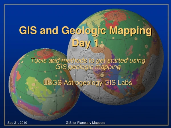
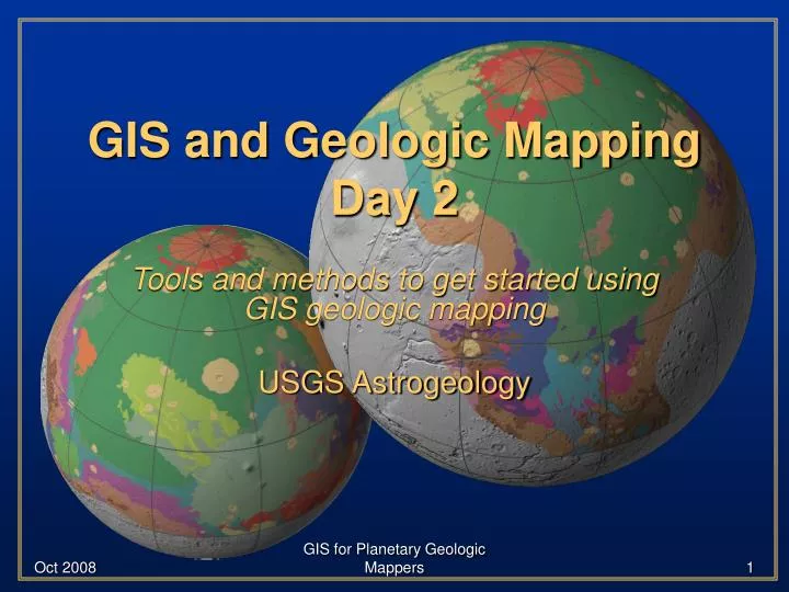
GIS and Geologic MappingDay 2 Tools and methods to get started using GIS geologic mapping USGS Astrogeology GIS for Planetary Geologic Mappers
Introduction • Goals • Data Models • Projections • Simple Lon, Lat Display • Data Registration • Loading Data • Querying and Spatial Statistics GIS for Planetary Geologic Mappers
Some important notes (cont’d) • Though this presentation is geared toward geologic mappers, the information is relevant to all GIS users • Screen-shots are likely to differ from individual views • GIS skills are developed through software interaction … be patient and try new things! Tip icon will point out helpful hints throughout the presentation GIS for Planetary Geologic Mappers
GIS Support • ESRI online portal to technical information • http://support.esri.com • ESRI ArcScripts • http://arcscripts.esri.com/ • ESRI Educational Services • Instructor-led training • Virtual Campus courses • Web workshops • Books GIS for Planetary Geologic Mappers
GIS Support Nodes • Planet-specific information (e.g., data, discussion, tutorials) • http://webgis.wr.usgs.gov/ • USGS discussion board (login required) • http://isis.astrogeology.usgs.gov/ … navigate to “Support” “Planetary GIS Discussions” “Plugging keywords into a internet search engine is a great way to search for GIS-related assistance!” GIS for Planetary Geologic Mappers
Transition • Data models – quick overview GIS for Planetary Geologic Mappers
3 43 12 3 45 (v1,v2) 15 40 2 15 24 V 21 3 5 10 64 Geographic Data Models • Vector and Raster - two main families • Representation of geographic information: • Raster: location controlled, attribute measured • values are stored in ordered array, so that position in the array defines geographic location • Vector: attribute controlled, location measured • geographic coordinates are stored separately from attributes, connected with Identifiers GIS for Planetary Geologic Mappers
Flat File Vector-based line 4753456 623412 4753436 623424 4753462 623478 4753432 623482 4753405 623429 4753401 623508 4753462 623555 4753398 623634 Raster-based line Flat File 0000000000000000 0001100000100000 1010100001010000 1100100001010000 0000100010001000 0000100010000100 0001000100000010 0010000100000001 0111001000000001 0000111000000000 0000000000000000 Rasters and Vectors GIS for Planetary Geologic Mappers
Rasters • Each cell can be owned by only one feature. • Rasters are easy to understand, easy to read and write, and easy to draw on the screen. A grid or raster maps directly onto an array. • Grids are poor at representing points, lines and areas, but good at surfaces. • Grids are a natural representation for scanned or remotely sensed data. • Grids suffer from the mixed pixel problem. GIS for Planetary Geologic Mappers
The mixed pixel problem GIS for Planetary Geologic Mappers
Methods of Grid Encoding • point-based • center point (regular grid) -DEMs, - but what if periodicity in landscape?; what if pop. density? • systematic unaligned (random in a cell) • area-based(have to integrate info...) • extreme value (max or min) • total (sum, like reflected light) • predominant type (most common) • presence/absence (binary result) • percent cover (% covered by single category) • precedence of types (highest ranking) GIS for Planetary Geologic Mappers
Discrete (categorical) Legend Mixed conifer Douglas fir Oak savannah Grassland Raster representation. Each color represents a different value of a nominal-scale field denoting land cover class. GIS for Planetary Geologic Mappers
Next Projections GIS for Planetary Geologic Mappers
Map projections • Define the spatial relationship between locations on earth and their relative locations on a flat map • Are mathematical expressions • Cause the distortion of one or more map properties (scale, distance, direction, shape) GIS for Planetary Geologic Mappers
Map projections A map projection is a set of rules for transforming features from the three-dimensional earth onto a two-dimensional display. No flat representation of the earth can be completely accurate, so many different projections have been developed, each suited to a particular purpose. Map projections differ in the way they handle four properties: Area, Angles, Distance and Direction. Rules: • No projection can preserve all four simultaneously, although some combinations can be preserved, such asArea and Direction • No projection can preserve both Areaand Angles, however. The map-maker must decide which property is most important and choose a projection based on that. GIS for Planetary Geologic Mappers
Map projections GIS for Planetary Geologic Mappers
Different Plane Locations and Viewpoints Normal or Polar Oblique Transverse orEquatorial GIS for Planetary Geologic Mappers
Different families of projections azimuthal conic cylindrical GIS for Planetary Geologic Mappers
Classification of map projections • Conformal – local shapes are preserved • Equal-Area – areas are preserved • Equidistant – distance from a single location to all other locations are preserved • Azimuthal – directions from a single location to all other locations are preserved GIS for Planetary Geologic Mappers
Standard projections • Standard projections in planetary • Simple Cylindrical (Equidistance Cylindrical, Equirectangular) • rectangular global (decimal degrees or meters), simple “database” projection. • Sinusoidal • Used for global and many tiled data releases, equal area projection. • Mercator • Conformal, only use for equatorial areas, used in the Mars 1:5M series. • Transverse Mercator • Good for local areas “large” scale maps. A Small scale map shows more land area, but with smaller representations and, therefore, lesser detail. GIS for Planetary Geologic Mappers
Standard projections – cont’d • Standard projections in planetary • Polar Stereographic • Good for polar, error increases away from central latitude (usually 90 or -90). Scale should be based on polar radius, can use polar radius. • Lambert Conformal • Good for mid latitudes. Error increases away from both standard parallels. • Orthographic • Globe view, not good for mapping as the limb falls away, makes for pretty figures but you need 3 globes to portray an entire planet. ISIS uses a spherical equation • Mollweide • Coming of age projection, global GIS for Planetary Geologic Mappers
Standard projections – cont’d • Other projections in planetary • Lambert Azimuthal • Good for mid latitude and polar, equal area, VICAR/HRSC team uses it for polar areas. • Robinson • Good for figures (similar to Mollweide) GIS for Planetary Geologic Mappers
Geographic – Geocentric Issues • Planetographic vs Planetocentric - issues • Mars is basically the only problem • Most commercial commonly don’t use ocentric - ArcMap can. • Work around … use sphere definition for Mars. • For commercial applications, don’t use elliptical definitions and ocentric latitudes. Using elliptical and ographic is okay. GIS for Planetary Geologic Mappers
East-West Longitude • Positive East vs. Positive West • Not much to say because commercial GIS/RS systems use positive East. You should always save your files using positive East. • To use West, you either fake out the system (by using your own code) or you switch software. It is just a shift, so no errors are incurred. • Luckily, if you are working in meters there is no East/West system, only Cartesian (X,Y). GIS for Planetary Geologic Mappers
Setting Projections in Arc • Use toolbox under ArcCatalog to set dataset’s projection • Toolbox: • ArcCatalog (data properties) To set many files, under toolbox samples – use batch define projection GIS for Planetary Geologic Mappers
Setting Projections in Arc • Setting planetary bodies in ArcMap • Example for decimal degree (lat/lon) • Okay to set ”Mars 2000.prj” ellipse. (find under “Coordinate Systems\Geographic Coordinate Systems\Solar System\Mars 2000.prj”) (semi-major radius 3396190 m) GIS for Planetary Geologic Mappers
Setting Projections in Arc • Example for the ArcMap dataframe or for MOLA and most raster datasets on the data DVD. • To define a new projection click on New, “Projected” GIS for Planetary Geologic Mappers
Setting Projections in Arc • Mars Polar projection • Note the “D_Mars_2000_Sphere_Polar” definition (semi-minor radius 3376200.0 m ) GIS for Planetary Geologic Mappers
Setting Projections in Arc • Projecting datasets using toolbox Projecting vector Projecting raster datasets GIS for Planetary Geologic Mappers
Hands-on (lon/lat display and data frame projections) GIS for Planetary Geologic Mappers
Display Lon, Lat Table • Create comma delimited text file (MSL.csv) Name, Lat, Lon Eberswalde, -23.86, 326.73 Holden, -26.37, 325.10 Gale, -4.49, 137.42 Mawrth, 24.65, 340.09 Nili Fossae, 21.01, 74.45 GIS for Planetary Geologic Mappers
Load Table 1. 2. GIS for Planetary Geologic Mappers
2. Display X,Y Data (lat,lon) Right click table 3. 1. 4. GIS for Planetary Geologic Mappers
Save to Permanent Right click points GIS for Planetary Geologic Mappers
Landing Site Error “Ellipse” Open Toolbox Add Data if needed GIS for Planetary Geologic Mappers
Transition • Simple Image Registration GIS for Planetary Geologic Mappers
* Worldfile • Most simple image registration 5.0 (size of pixel in x direction) – A 0.0 (rotation term for row) - D 0.0 (rotation term for column) - B -5.0 (size of pixel in y direction) - E 492169.690 (x coordinate of center of upper left pixel in map units) - C 54523.3180 (y coordinate of center of upper left pixel in map units) - F GIS for Planetary Geologic Mappers
Worldfile • Algebraic Form (six parameter affine transformation) x’ = Ax + By + C y’ = Dx + Ey + F where x’ = calculated x-coordinate of the pixel on the map y’ = calculated y-coordinate of the pixel on the map x = column number of a pixel in the image y = row number of a pixel in the image A = x-scale; dimension of a pixel in map units in x direction B,D = rotation terms (assumed to be zero) C,F = translation terms; x,y map coordinates of the center of the upper-left pixel E = negative of y-scale; dimension of a pixel in map units in y direction GIS for Planetary Geologic Mappers
PDS Worldfile • PDS uses same – but X,Y are in “pixel” space Worldfile (MOLA 4ppd megt90n000cb.lbl) OBJECT = IMAGE_MAP_PROJECTION ^DATA_SET_MAP_PROJECTION = "DSMAP.CAT" MAP_PROJECTION_TYPE = "SIMPLE CYLINDRICAL" A_AXIS_RADIUS = 3396.0 <KM> B_AXIS_RADIUS = 3396.0 <KM> C_AXIS_RADIUS = 3396.0 <KM> FIRST_STANDARD_PARALLEL = "N/A" SECOND_STANDARD_PARALLEL = "N/A" POSITIVE_LONGITUDE_DIRECTION = "EAST" CENTER_LATITUDE = 0.0 <DEGREE> CENTER_LONGITUDE = 180.0 <DEGREE> REFERENCE_LATITUDE = "N/A" REFERENCE_LONGITUDE = "N/A" LINE_FIRST_PIXEL = 1 LINE_LAST_PIXEL = 720 SAMPLE_FIRST_PIXEL = 1 SAMPLE_LAST_PIXEL = 1440 MAP_PROJECTION_ROTATION = 0.0 MAP_RESOLUTION = 4.0 <PIXEL/DEGREE> MAP_SCALE = 14.818 <KM/PIXEL> MAXIMUM_LATITUDE = 90.0 <DEGREE> MINIMUM_LATITUDE = -90.0 <DEGREE> WESTERNMOST_LONGITUDE = 0.0 <DEGREE> EASTERNMOST_LONGITUDE = 360.0 <DEGREE> LINE_PROJECTION_OFFSET = 360.5 SAMPLE_PROJECTION_OFFSET = 720.5 COORDINATE_SYSTEM_TYPE = "BODY-FIXED ROTATING" COORDINATE_SYSTEM_NAME = "PLANETOCENTRIC" END_OBJECT = IMAGE_MAP_PROJECTION 14818.0 (meters) 0.0 0.0 -14818.0 -10676369.0 X = SAMPLE_PROJ_OFFSET * MAP_SCALE * -1 5341889.0 Y = LINE_PROJ_OFFSET * MAP_SCALE http://pds-geosciences.wustl.edu/missions/mgs/megdr.html GIS for Planetary Geologic Mappers
Transition • Loading PDS and ISIS2,3 Images GIS for Planetary Geologic Mappers
How to use low-level PDS • Low-level PDS image is basically “raw” – no map projection – you should not bring it into a GIS • Okay how do you map project raw PDS image • ISIS - Integrated Software for Imagers and Spectrometers • Suse Linux, Solaris UNIX, Mac OSX http://isis.astrogeology.usgs.gov/ • VICAR - Video Image Communication And Retrieval http://www-mipl.jpl.nasa.gov/ also maintained at DLR GIS for Planetary Geologic Mappers
How to use low-level PDS http://isis.astrogeology.usgs.gov/IsisSupport/viewtopic.php?t=423 Why: In short, these programs radiometrically correct the image (level 1) and then geometrically project it through the MOLA DEM to the surface via the spacecraft pointing parameters (SPICE). Again, this is the only way to accurately position the images to the surface for ArcMap or other GIS/RS software. So without “orthorectification” you should not use as a GIS base. Once a level2 ISIS image is generated, you can use the included ISIS tools or standalone PERL scripts to make them ArcMap compatible as described here: http://isis.astrogeology.usgs.gov/IsisSupport/viewtopic.php?t=357 or http://isis.astrogeology.usgs.gov/IsisSupport/viewtopic.php?t=358The ERDAS raw format works well in ArcMap for multi-band 32bit images like THEMIS. However, when possible it is still a good idea to convert to 8 bit. GIS for Planetary Geologic Mappers
Using High-level PDS files PERL script to add GIS header:> pds2world.pl -e -prj pdsimage.img Outputs ERDAS raw header. The “-prj” flag supports creation of a Projection file. for image with detached PDS labels > pds2world.pl -e -prj pdsimage.lbl Outputs ERDAS raw header. The “-prj” flag supports creation of a Projection file. http://webgis.wr.usgs.gov/pigwad/tutorials/scripts/perl.htm GIS for Planetary Geologic Mappers
Using High-level PDS files More on pds2world.pl (pds2world.exe also available for Windows) Command line: pds2world.pl [-bit=8|16] [-r|-g|-t|-c|-j|-p] [-prj] input.img -r = output raw header and worldfile -e = output ERDAS raw header and worldfile (8, 16, 32 bit) -g = output gif worldfile -t = output tif worldfile -j = output jpeg worldfile -J = output jpeg2000 worldfile -P = output png worldfile -p = output PCI Aux header (8, 16, 32 bit) -c = output img header and worldfile (default) -prj = create ESRI Well Known Text projection file *.prj Examples: Create files for 32 bit ERDAS: pds2world.pl -e input.img ---- (good for ERDAS and ArcMap) Create files for 32 bit ERDAS: pds2world.pl -p input.img ---- (good for GDAL and GDAL conversion) Create worldfile for tif: pds2world.pl -t input.img ---- (needs another application to convert pds to Tiff) GIS for Planetary Geologic Mappers
How to use high-level ISIS2 http://isis.astrogeology.usgs.gov/IsisSupport/viewtopic.php?t=357 Does ISIS2 have any routines to convert to an GIS compatible format? There exist ISIS PERL scripts that one can run on the ISIS files to extract this information into header and worldfiles. These ISIS scripts are:dform.plConvert an ISIS image from 32 or 16 bit to an 8 bit GIS raw, tiff, gif, jpeg with detached GIS files. dform will automatically try to choose a stretch pair for conversion to 8 bit. The user can also specify the stretch pair. isis2gisworld.plCreates GIS headers and GIS worldfiles for ISIS images so that they can be read into most GIS packages. If you are using ArcMap or ERDAS and wish to maintain a 32 bit file use the ERDAS raw switch " -e ". Examples: Converting to an 8bit Tiff with GIS headers: > dform.pl -t -bit=8 -gis=yes isis2image.cub You will end up with two files - the Tiff image, and a Tiff worldfile. Converting to an 8bit Jpeg with GIS headers: > dform.pl -j=75 -bit=8 -gis=yes isis2image.cub "-j=75" is the Jpeg compression quality (100 is the best). Here, you will end up with two files - the Jpeg image, and a Jpeg worldfile. Creating GIS headers for a 32bit ISIS cub:> isis2gisworld.pl -e isis2image.cubYou will end up with three files - the ISIS image, a header file "*.raw", and a worldfile "*.rww". This is called an ERDAS raw format. In your GIS you will need to set the NULL ISIS value (more below). GIS for Planetary Geologic Mappers
High-level ISIS2 files w/o ISIS2 PERL script to add GIS header:> isis2world.pl -e –prj isis2image.cub Outputs ERDAS raw header. The “-prj” flag supports creation of a Projection file. http://webgis.wr.usgs.gov/pigwad/tutorials/scripts/perl.htm Converting a 16, 32bit ISIS cub to an ESRI ASCII format:> isis2arc myinput.lev2.cub myoutput.ascFree stand-alone C applicaiton (link) GIS for Planetary Geologic Mappers
Using High-level ISIS2 files More on isis2world.pl (isis2world.exe also available for Windows) Command line: isis2world.pl [-bit=8|16] [-r|-g|-t|-c|-j|-J|-p|-P|-w] [-prj] input.cub -r = output raw header w/ georefencing (8, 16 bit) -e = output ERDAS raw header and worldfile (8, 16, 32 bit) -g = output gif worldfile -t = output tif worldfile -w = output generic *.wld worldfile -J = output jpeg2000 worldfile -j = output jpeg worldfile -P = output a png worldfile -p = output PCI Aux header w/ georefencing (8, 16, 32 bit) -c = output cub header w/ georef (default) (8, 16 bit) -prj = create ESRI Well Known Text projection file *.prj Examples: Create files for 32 bit ERDAS w/ Projection: isis2world.pl -e -prj input.cub ----- (good for ERDAS and ArcMap) Create header for 32 bit PCI Aux: isis2world.pl -p input.cub ----- (good for GDAL conversion) Create worldfile for tif: isis2world.pl -t input.cub ----- (needs program to convert ISIS file to Tiff) GIS for Planetary Geologic Mappers
How to use high-level ISIS3 ISIS3 can convert images to GIS compatible format Isis2std – creates 8bit only JPEG, PNG (TIFF) with automatic worldfile Examples: Converting to an 8bit Tiff with GIS headers: > Isis2std format=PNG from=myinput.lev2.cub to=myoutput.png You will end up with two files - the png image, and a png worldfile. http://isis.astrogeology.usgs.gov/IsisSupport/viewtopic.php?t=357 GIS for Planetary Geologic Mappers
High-level ISIS3 files w/o ISIS3 PERL script to add GIS header:> isis3world.pl -e –prj isis3image.cub Outputs ERDAS raw header. The “-prj” flag supports creation of a Projection file. http://webgis.wr.usgs.gov/pigwad/tutorials/scripts/perl.htm Note that ISIS3 uses a raw “tiled” internal format. This makes supporting this as a generic raw format harder. The ERDAS raw format fortunately supports tiled images. Other formats may require ISIS3 to output a “BSQ” format instead of a “tiled” format. ISIS3 example: >crop from=input.cub to=output.cub+bsq GIS for Planetary Geologic Mappers
Using High-level ISIS3 files More on isis3world.pl (isis3world.exe also available for Windows) Command line: isis3world.pl [-bit=8|16] [-r|-g|-t|-c|-j|-J|-p|-P|-w] [-prj] input.cub -r = output raw header w/ georefencing (8, 16 bit) -e = output ERDAS raw header and worldfile (8, 16, 32 bit) -g = output gif worldfile -t = output tif worldfile -J = output jpeg2000 worldfile -j = output jpeg worldfile -P = output a png worldfile -p = output PCI Aux header w/ georefencing (8, 16, 32 bit) -c = output cub header w/ georef (default) (8, 16 bit) -prj = create ESRI Well Known Text projection file *.prj Examples: Create files for 32 bit ERDAS w/ Projection: isis3world.pl -e -prj input.cub ----- (good for ERDAS and ArcMap) Create header for 32 bit PCI Aux: isis3world.pl -p input.cub ----- (requires “BSQ” isis3 file, for GDAL conversion) Create worldfile for tif: isis3world.pl -t input.cub ----- (needs program to convert ISIS file to Tiff) GIS for Planetary Geologic Mappers