Download

1 / 52
550 likes | 1.15k Views
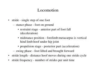
Locomotion Interfaces. John M. Hollerbach School of Computing University of Utah http://www.cs.utah.edu/~jmh/Locomotion.html. Types of Motion Interfaces. 1. Passive motion interfaces. Non-inertial systems (e.g., joysticks) Inertial systems (e.g., Stewart platforms).

E N D
Locomotion Interfaces John M. Hollerbach School of Computing University of Utah http://www.cs.utah.edu/~jmh/Locomotion.html
Types of Motion Interfaces 1. Passive motion interfaces • Non-inertial systems (e.g., joysticks) • Inertial systems (e.g., Stewart platforms) 2. Active motion interfaces • Normal rooms with CAVE or HMD displays • Locomotion interfaces (e.g., exercise machines)
Features of Motion Interfaces 1. Passive motion interfaces • Rate control is used. • User is seated and does not expend energy. 2. Locomotion interfaces • Cyclic proportional control is used. (gait) • User expends energy to move through VE. • Sensorimotor integration for geometry.
Proposed Applications • Training and mission rehearsal. • Architectural walkthroughs. • Education. • Mobile robot interface (virtual tourist). • Entertainment: arcades and exercise. • Health rehabilitation. • Psychological research.
Types of Locomotion Interfaces • Pedaling devices • Walking-in-place systems • Programmable foot platforms • Treadmills
Pedaling Devices Hodgins, Georgia Tech Sarcos Uniport
Walking-in-place systems Templeman’s Gaiter system, NRL
Programmable Foot Platforms Sarcos Biport Iwata’s GaitMaster
Linear Treadmill Devices Sarcos Treadport ATR ATLAS ATR GSS (ground surface simulator)
Planar Treadmill Devices Omni-Directional Treadmill Torus Treadmill
Treadport II Specifications • 6x10 foot white belt • 12 mph belt speed, 1 g belt acceleration • 5% belt slowdown at 750 lb normal force • +/- 20 degrees tilt in 1 second • 70 lbs tether force at 3 Hz
Locomotion Display Issues • Unilateral constraints • Linear motion • Turning • Slope and uneven terrain
Active Mechanical Tether Uses • Centering force f = k x • Unilateral constraint force f = k x - b v • Gravity force f = m g sin q • Inertial force f = m a
Unilateral Constraints • We should not be able to walk through objects. • Braking the locomotion interface is not enough --- the user stumbles forward. • Tether wall force f = k x - b v
Linear Motion Display The Treadport allows • Normal human gait • Varied movements and postures • Inertial force display
Missing Inertial Force • Running on a treadmill requires much less energy than running on the ground. - 35% less energy when replaying 100y dash. - The body is stationary w.r.t. the ground. • Modulating treadmill belt speed can only partially compensate. • Active mechanical tether can supply missing inertial force.
Inertial Force Feedback f = m a
Evaluation of Tether Force Strategies 3. No tether force: f = 0 - Unstable running. 2. Spring force: f = k x - k fixed for all users. 1. Inertial force f = 0.8 m a - Universally preferred. - Partial force preference.
Slope Display • Tilt mechanism is rather slow. • Fast slope transients cannot be displayed by tilt. • Tilting complicates ground projection and CAVE display. • Tether force can simulate gravity and slope.
Slope Walking g m g sin q m q mg q
Gravity Feedback F = m g sin q
Psychological Slope Experiments • Subjects walked on treadmill tilted at angle q. • Subjects then walked on the leveled treadmill. • Tether force f was adjusted until the subjects judged “equivalence.”
Biomechanical Measurements • Optotrak markers • Rigid bars on leg segments • Comfortable but firm mountings • Joint angles calculated from vector relations
Derived Force versus Slope Hip range vs. force: HR = a f + b User 1 2 3 4 5 6 (c/a) -437 -289 -494 -444 -576 -480 (d-b)/a 2.0 -15.5 -19.8 -17.9 32.0 3.6 Hip range vs. slope: HR = c q + d Force vs. slope: f = (c/a) q + (d-b)/a
Force/slope normalized by mass User 1 2 3 4 5 6 (c/a/m) 0.647 0.520 0.756 0.526 0.730 0.663 Psychophysical result: f = 0.65 m g q
Tether Force Realistically Simulates Slope • Psychologically equivalent. • Biomechanically equivalent. • A platform tilt mechanism is not needed.
Partial Force Preference • Slope rendering: f = 0.65 m g sin q • Inertia rendering: f = 0.8 m a Possible Explanations • Non-distributed force application to body • Oversimplified locomotion dynamics model
Belt Motor Sizing • Load is predominantly friction force from impact • Impact forces are 3-6 times body weight • Design specification is slowdown < 5% • A 5 Hp motor handles a 90 kg with mu=0.15 • An 8 Hp motor chosen
Tether Force Requirements • Inertial force display • Suppose m = 90 kg, a = 10 m/s^2 f = m a = 900 N • Safety concerns with 900 N force applied to the back • Reduce required tether force by allowing some actual acceleration on the belt
Running model: x = (v /k) (exp(-kt) + kt - 1)(Hill’s equation)
Simulation of Required Tether Force • Controller was tuned to allow • 0.8m forward movement • Tether force reduced to 350N • 80% preference = 280N • Design set at 315N • Acceptable load on back
Harness Design Issues • Mechanical coupling for pushing is good (metal plate against the backbone) • Mechanical coupling for pulling is a problem • Backlash due to straps and soft tissue • Metal plate lifts off • Better strapping must also consider different people sizes, sexes, and comfort
Visual Display CAVEs • High resolution and brightness (no stereo yet) • Seeing your body increases immersion (and safety) • Panorama views not convenient with treadmills • Objects are mostly at a distance HMDs • Panorama and stereo viewing • Low optical quality and resolution • Safety, encumbrance, and body image
System Safety • Vertical motion restraint • Mechanical limit stops on tether • Limit switches on tether • Hardware springs at base and endpoint for twist, software spring for forward motion • Kill switches by user and operator • Watchdog timer • Software bounding box, and limits on velocity, acceleration, force, and force rate
System Safety (cont) • Human subjects committee approval • Consent form • Tourist versus expert settings • No minors
What are the Design Tradeoffs? We can’t display completely natural locomotion yet because of device limitations. What aspects are most important and how are they best implemented? • Platform motions (planar, tilt, deformed belt) vs. or with Whole-body force feedback • CAVEs vs. HMDs for visual display • Platform motions may interfere with CAVEs.