Download
1 / 19
350 likes | 604 Views
IMPROVING DIRECT TORQUE CONTROL USING MATRIX CONVERTERS. Technical University of Catalonia. Electronics Engineering Department. Colom 1, Terrassa 08222, Catalonia, Spain. University of Malta. Department of Electrical Power and Control Engineering. Msida MSD 06, Malta.

E N D
IMPROVING DIRECT TORQUE CONTROL USING MATRIX CONVERTERS Technical University of Catalonia. Electronics Engineering Department. Colom 1, Terrassa 08222, Catalonia, Spain University of Malta.Department of Electrical Power and Control Engineering. Msida MSD 06, Malta Home Supervisor: Dr. Antoni Arias Pujol Malta Supervisor: Dr. Cedric Caruana Research Student: Carlos Ortega García
Index • Introduction • Matrix Converters. • Direct Torque Control. • Classical • Using Matrix Converters. • Sensorless Control of a DTC drive using hf injection • Conclusions.
Introduction Matrix Converters (MC) • Advanced circuit topology capable of generating AC-AC. • Load voltage with arbitrary amplitude and frequency, and sinusoidal input/output waveforms. • Power Factor Correction (PFC). • No inductive or capacitive elements are required, thus allowing a very compact design. • A very good alternative to Voltage Source Inverters (VSI).
Introduction Direct Torque Control (DTC). • Simple and robust signal processing scheme. • No coordinate transformation and no PWM generation are needed. • Quick and precise torque response. • The torque and flux modulus values and sector of the flux are needed. • High torque ripple.
Introduction High Frequency Signal Injection. • Non Model-Based method. • Avoids problems at low and zero speed due to the lack of back-EMF. • No dependence of machine parameters. • Saliency required.
Introduction Main objectives: • Improve the Direct Torque Control, regarding torque ripple, using small vectors of Matrix Converters. • Analysis of different High Frequency signal Injection methods for sensorless Direct Torque Control.
State of the Art Matrix Converters • A switch, Sij, i={A,B,C}, j={a,b,c} can connect phase i of the input to phase j of the load. • Switches states characterized by: A mathematical model of the MC can be derived: • Voltage equations: • Current equations:
State of the Art Matrix Converters • Since any output phase can be connected to any input phase, there are 27 possible switching configurations. • Applying Clark’s transformation to all switching states, it can be found that MC can generate: • 18 active vectors, 6 rotating vectors, and 3 zero vectors. Output line-to-neutral voltage vectors Input line current vectors
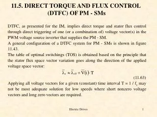
Direct Torque Control • Stator flux y*sand torque T*e references are compared with the corresponding estimated values. • Both stator flux and torque errors, Ey and ETe, are processed by means of hysteresis band comparators. • A proper VSI voltage vector is selected. • The flux vector reference and the hysteresis band tracks a circular trajectory, thus, the actual flux follows its reference within the hysteresis band in a zigzag path.
Direct Torque Control using Matrix Converters Classical DTC using Matrix Converters • Matrix converter generates a higher number of output voltage vectors with respect to a VSI. • Another variable, <sin f>, is introduced to control the input power factor. • Keeping this variable close to zero, unity power factor operation is possible. • A new hysteresis comparator is introduced which controls this variable. Direct Torque Control for Induction Motors Using Matrix Converters (CPE-05)
Direct Torque Control using Matrix Converters The use of small vectors of Matrix Converters • A new torque hysteresis comparator will provide four different levels instead of three to distinguish between small and large positive and negative torque errors. • Large vectors will be used when large torque error is detected. • When torque error is small, the small voltage vector will be applied. • Zero vectors will be applied if small torque error is detected and back EMF imposes a variation in torque towards its reference value.
Direct Torque Control using Matrix Converters The use of small vectors of Matrix Converters Torque ripple performance. Comparison between the classical use of MC in DTC and the proposed method. wref=100% rated speed and TL=100% rated torque. Classical DTC using MC Proposed method
Direct Torque Control using Matrix Converters The use of small vectors of Matrix Converters Torque ripple performance. Comparison between the classical use of MC in DTC and the proposed method. • The use of zero and large vectors in the classical method leads into an over/undershoot, more pronounced as the speed increases. • Small vectors are more effective keeping the torque within the its reference bands.
b g L min m g q max r q a g g min max q r(elec) (b) (a) Sensorless Control Saliency • Asymmetry in the machine. • Magnetizing inductance variation. • Asymmetry in the rotor Rotor Position.
Sensorless Control a-bframe rotating injection. • Straightforward in vector controlled drives. • The carrier can be superimposed to the voltage reference.
Sensorless Control a-binjection in a DTC drive. • Flux and Torque processed errors, Hys and HTe, converted directly to switching signals. • No voltage command => Difficult to inject. • Injection directly modifying the vector pattern imposed by the DTC switching table. • High bandwidth of hysteresis controllers. • Difficult to inject outside of this bandwidth. • Decoupling of fundamentaland hf currents is necessary
Sensorless Control a-binjection in a DTC drive. Comparison between real and estimated position Steady state at 375 rpm Speed reversal.
Conclusions • Advantages of Matrix Converters over the traditional VSI has been combined with the advantages of the DTC scheme. • The use of small vectors of the MC has been investigated. • High frequency injection in a DTC drive has been presented.