Download
1 / 22
230 likes | 353 Views
The Status of COS Flat Fields. Tom Ake TIPS 21 August 2008. Status of COS Flat Fields. Material covered today COS Description and Signal-to-Noise Requirements NUV Ground Calibration and SMOV4 Plans FUV Detector Characteristics FUV Ground Calibration and SMOV4 Plans

E N D
The Status of COS Flat Fields Tom Ake TIPS 21 August 2008
Status of COS Flat Fields • Material covered today • COS Description and Signal-to-Noise Requirements • NUV Ground Calibration and SMOV4 Plans • FUV Detector Characteristics • FUV Ground Calibration and SMOV4 Plans • Most of the results are from COS IDT analyses • Thermal Vac 2003 at Ball Aerospace • Thermal Vac 2006 at GSFC
COS Detector Overview • COS comprised of two spectrograph channels with two different types of micro channel plate (MCP) detectors
COS S/N Requirements • Designed to obtain S/N = 30 per resel routinely, 100 per resel with special effort • S/N requirements achieved by various techniques • Flat fielding to divide out small scale fixed pattern noise • FP-POS grating steps to average out small scale fixed pattern noise • Pulse height amplitude (PHA) screening (FUV time-tag only) • As a performance metric, the S/N ratio is taken to be the reciprocal of the RMS scatter around a smooth fit to the data
Example of Detector Artifacts • Features correctable by flat fielding • Hex pattern • Moiré pattern • Divots/blemishes • Grid wire shadows (on FUV only) • Uncorrectable features • Dead spots • Hot spots • Spectrum location not known until SMOV4 alignment
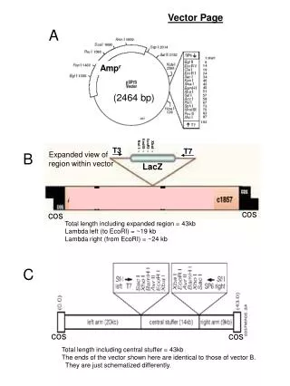
Flat Field Calibration • Internal calibration system consists of two deuterium lamps illuminating a flat field calibration aperture (FCA) • Light takes nearly the same optical path as an external target • Only the science areas of the detectors are illuminated, not the wavelength calibration region • FCA (X=1750 µm, Y= 750 µm) is larger than the PSA (700 µm diameter) • Aperture mechanism moves in both dispersion and cross-dispersion directions • External flat field calibration exposures were taken through the PSA during thermal vacuum tests in 2003 and 2006 • Preserved internal lamp • Allowed characterization of illumination angle dependence between PSA and FCA
NUV Ground Calibration • G185M grating used since D2 lamp throughput has peak continuum flux there • Internal and external exposures taken at various FCA Y positions to paint science area • Internal data - 210 counts/pixel in 65 Ksec • External lamps - 8700 counts/pixel in 25 Ksec • Superflat constructed from all data • Polynomial fits performed along dispersion for L-flat • Total counts high enough to yield pixel-to-pixel variations (P-flat) • S/N = 95 from photon statitsics
NUV Flat Field Assessment • Distribution of P-flat variations give maximum S/N without a flat field • Histogram of variations in each NUV stripe fit with Gaussian profile • Widths indicate S/N (= 1/) ~ 50 per resel can be obtained without a flat • NUV high quality test spectrum obtained using external D2 lamp through O2 absorption cell • Extracted spectrum with slit 25 pix high in cross-dispersion direction • Compare run of S/N with count level • S/N ~ 100 realized with FP-POS and flat fielding Penton Penton
NUV SMOV4 Calibration • Since MAMA pixels are mapped to physical anode wires, expect ground superflat will be valid • Flat field will be used by CalCOS • Baseline plan is to replicate TV2003 internal lamp exposures (60 Ksec with G185M grating) • Only nominal Y location of FCA • Mapping in Y performed by using different gratings • On-orbit data will achieve S/N ~ 15 per pixel (~ 45 per resel) • New P-flat will be compare to ground flat to verify it has not changed • If there is a difference, another set of exposures taken in SMOV4 • If necessary, more taken during Cycle 17 calibration
FUV Detector Characteristics • The FUV XDL detector is inherently different from the NUV MAMA • Photon locations are defined by the difference in time it takes for the MCP charge cloud pulse to reach the ends of the delay lines • Positions needs to be thermally corrected using stim pulses and geometrically corrected to equalize pixel area • COS team prefers the term “detector element” to “pixel” since the pixels are not physical • In time-tag mode, PHA data provide measure of charge cloud produced by the photon, which is a function of the gain distribution at each pixel
FUV Detector Gain • Detector gain can be important for flat fields • Photon position errors can arise from pulse shape differences at different PHAs • Detector structures can be different • Noise reduction by eliminating low and high PHAs, which are not likely real photons • For COS, pulse height is digitized to values between 0-31 • Detector gain is not the same as sensitivity • Since detector is photon counting rather than charge integrating, intensity of charge cloud unimportant as long as event can be discerned above the noise
FUV Ground Calibration (TV2003) • The two segments of the FUV are treated separately • More spectral features in D2 occur in FUV region • To avoid D2 structure, G130M was used for FUVA, G160M for FUVB. This doubled the amount of exposure time needed. • 95 internal D2 lamp exposures were taken at all central wavelengths and FP-POS positions • 19 Ksec per segment • Yielded median counts of 276 (FUVA) and 296 (FUV B) per pixel • S/N ~ 18 per pixel (~130 per resel ) • External lamp data not useful due to low lamp throughput, so no supplemental data used to create a ground flat
FUV Flat Field Assessment (TV2003) • As with NUV, L-flats and P-flats constructed for each segment • S/N ~ 5/6 per detector element • Maximum S/N without a flat field estimated to be ~20 per resel • FUV high quality spectrum test with CO absorption cell and Kr lamp • S/N >30 obtained with FP-POS technique • TV2003 flat did not improve data beyond what could be achieved with FP-POS • Plateau in S/N reached at ~ 2000 counts Penton Penton
FUV Ground Calibration (TV2006) • In TV2006, the calibration system delivered more light from the external D2 source than the TV2003 set up • External source produced continuum only > 1600 Å, so long wavelength portion of segment A analyzed • Series of tests conducted to investigate S/N characteristics from a 1-D flat field • Twenty high S/N exposures acquired to simulate a point source in the PSA • G160M grating used at 5 central wavelengths, 4 FP-POS settings each • Divided data into two sets of 10 exposures and used one set to flatten the other
FUV Flat Field Assessment (TV2006) • 1-D flat fields created and one group used to flatten the other • Data co-added in detector space and normalized by linear fit • Data aligned in wavelength space for S/N evaluation with and without flat fielding • S/N close to photon statistics achieved with flat fielding and FP-POS merging • Photon limited result factors in quality of the flat (estimated to be 3%) • No plateau in the S/N distribution, so maximum S/N achievable is higher • External flat should be obtained on-orbit since illumination appears to be important Penton Penton
FUV SMOV4 Calibration • No on-orbit D2 lamp exposures planned for SMOV4 • FASTEX standard observed in PSA with all gratings • Each grating has slightly different Y location (G140L top, G130M middle, G160M bottom of science area • Use Y POS-TARG steps in PSA to ±1.2” with 0.6” spacing to increase area covered • Spectra shifted to four locations in X by combination of central wavelength and FP-POS selections
FUV SMOV4 Calibration • Chose high declination DA white dwarf , WD0320-539 (V=14.9) • Provides count rate near time-tag limit (~ 20,000 counts/sec) so we can maximize counts and still obtain PHA data • Exposure times chosen to achieve S/N = 35-45 per resel • Will take 11 orbits • Data will be combined to create 2-D flat field using an iterative technique • Methodology first used with GHRS and described in STIS ISR 98-16 (Gilliland) • Iterate between wavelength and pixel space in merging and correcting data sets • Solve simultaneously for the stellar spectrum and underlying fixed pattern noise
COS Flat Field Summary • NUV flat field will be in good shape after SMOV4 • Enough counts obtained in TV to create P-flat at pixel level • Expect on-orbit flat field to be consistent with or correctable to ground flat • CalCOS set to perform flat field correction as default • FUV flat field requires more work • Investigating P-flat at resel level or 2-D S-flat • Uncertainty about flat field changes with detector aging • CalCOS currently set NOT to perform flat field correction, but can be turned on with a switch • Best technique for improving S/N is through an FP-POS strategy