Download

1 / 39
390 likes | 630 Views
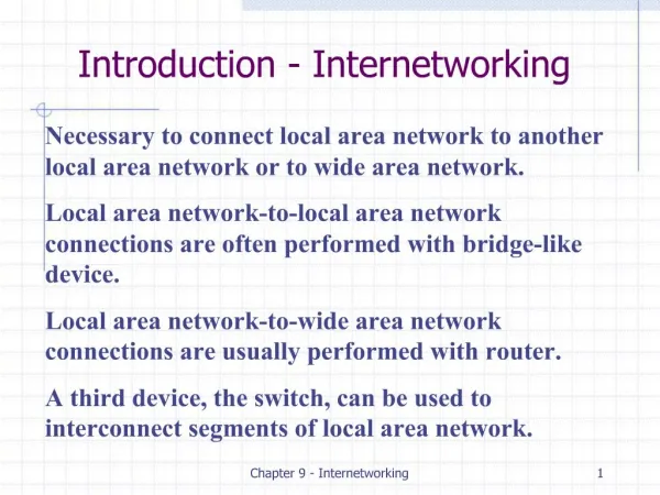
CHAPTER 1 Internetworking Concepts Overview. Defining components of Network OSI Model Overview TCP Operation. Chapter Objective. On completion of this chapter, you will be able to perform the following tasks: Describe how data traffic is exchanged between source and destination devices

E N D
CHAPTER 1Internetworking Concepts Overview Defining components of Network OSI Model Overview TCP Operation 640-802 CCNA
Chapter Objective 640-802 CCNA • On completion of this chapter, you will be able to perform the following tasks: • Describe how data traffic is exchanged between source and destination devices • Identify the roles and functions of a hub, switch, and router, and where they best fit in the network • Describe TCP operations, Windowing, Sequence number and Acknowledgment.
Defining components of Network (1) Home Office Mobile Users Internet Branch Office Main Office 640-802 CCNA
Defining components of Network (2) Branch Office Floor 2 Server Farm ISDN Floor 1 Telecommuter Remote Campus 640-802 CCNA
Network Structure Defined by Hierarchy Core Layer Distribution Layer Access Layer 640-802 CCNA
Access Layer Charactertistics Access Layer End station entry point to the network 640-802 CCNA
Distribution Layer Charactertistics • Access Layer Aggregation Point • Routes traffic • Broadcast/Multicast Domains • Media Translation • Security • Possible point for remote access Distribution Layer 640-802 CCNA
Core Layer Characteristics Core Layer • Fast transport to enterprise services • No packet manipulation 640-802 CCNA
OSI Model Overview (1) Application Application (Upper) Layers Presentation Session Transport Layer Data Flow Layers Network Layer Data Link Physical 640-802 CCNA
Role of Each Layer (1) EXAMPLES Telnet FTP Application User Interface ASCII EBCDIC JPEG • How data is presented • Special processing such as encryption Presentation Keeping different applications’ data separate Operating System/ Application Access Scheduling Session Transport Layer Network Layer Data Link Physical 640-802 CCNA
Role of Each Layer (2) Application Presentation Session TCP UDP SPX • Reliable or unreliable delivery • Error correction before retransmit EXAMPLES Transport Provide logical addressing which routers use for path determination IP IPX Network • Combines bits into bytes and bytes into frames • Access to media using MAC address • Error detection not correction 802.3 / 802.2 HDLC Data Link • Move bits between devices • Specifies voltage, wire speed and pin-out cables EIA/TIA-232V.35 Physical 640-802 CCNA
FCS FCS Data Encapsulation Application PDU Presentation Session Upper Layer Data Segment Transport TCP Header Upper Layer Data Network Packet IP Header Data LLC Header Data Data Link Frame MAC Header Data Physical Bits 0101110101001000010 640-802 CCNA
Data Decapsulation Application Presentation Session Upper Layer Data Transport Upper Layer Data TCP Header Network TCP+ Upper Layer Data IP Header Data Link IP + TCP + Upper Layer Data LLC Header LLC Hdr + IP + TCP +Upper Layer Data MAC Header Physical 0101110101001000010 640-802 CCNA
Written Exercise: OSI Model OSI Model PDU Examples Functional Responsibilities Application Presentation Session Transport Network Data Link Physical 640-802 CCNA
Physical Layer Functions • Defines • Media type • Connector type • Signaling type EIA/TIA-232 Physical 802.3 V.35 Ethernet 640-802 CCNA
Physical Layer/ Ethernet 802.3 10Base2—Thin Ethernet10Base5—Thick Ethernet Host Hub 10BaseT—Twisted Pair Hosts 640-802 CCNA
A C B D Hubs Operate at Physical Layer Physical • All devices in the same collision domain • All devices in the same broadcast domain • Devices share the same bandwidth 640-802 CCNA
Hubs: One Collision Domain • More end stations means more collisions • CSMA/CD is used 640-802 CCNA
Data Link Layer Functions (1) • Defines • Physical source and destination addresses • Higher layer protocol (Service Access Point)associated with frame • Network topology • Frame sequencing • Flow control • Connection-oriented or connectionless 802.2 Frame Relay Data Link HDLC Ethernet 802.3 EIA/TIA-232 v.35 Physical 640-802 CCNA
Data Link Layer Functions (2) MAC Layer - 802.3 # Bytes 8 6 6 2 Variable 4 Preamble Dest add Source add FCS Length Data Ethernet II uses “Type” here and does not use 802.2. • 0000.0C xx.xxxx IEEE assigned Vendor assigned • MAC Address 640-802 CCNA
Data Link Layer Functions (3) 802.2 (SNAP: Sub network Access Protocol) 1 1 1 or 2 3 2 Variable # Bytes Ctrl 03 OUI ID Source SAP AA Dest SAP AA Type Data OR 802.2 (SAP: Service Access Point) 1 1 1 or 2 Variable # Bytes DestSAP Source SAP Ctrl Data Specify next upper layer protocol 06= IP, E0=IPX Preamble Dest add Source add Length Data FCS MAC Layer - 802.3 640-802 CCNA
4 Switches and Bridges Operate at Data Link Layer Data Link OR 1 2 3 1 2 • Each segment has its own collision domain • All segments are in the same broadcast domain 640-802 CCNA
Switches Switch Memory • Each segment has its own collision domain • Broadcasts are forwarded to all segments 640-802 CCNA
Network Layer Functions (1) • Defines logical source and destination addresses associated with a specific protocol • Defines paths through network • Interconnects multiple data links IP, IPX Network 802.2 Data Link Frame Relay HDLC Ethernet 802.3 EIA/TIA-232 v.35 Physical 640-802 CCNA
Network Layer Functions (2) Network Layer End Station Packet Sourceaddress Destination address Data IP Header • 172.15.1.1 • Logical Address Node Network 640-802 CCNA
Network Layer Functions (3) Address Mask 172.16.122.204 255.255.0.0 172 16 122 204 11001100 00010000 10101100 01111010 BinaryAddress 255 255 0 0 11111111 11111111 00000000 00000000 BinaryMask Network Host 640-802 CCNA
Network Layer Functions (4) 1.0 4.0 1.1 4.1 2.1 2.2 1.3 4.3 1.2 4.2 E0 S0 S0 E0 • Logical addressing allows for hierarchical network • Configuration required • Uses configured information to identify paths to networks 640-802 CCNA
Routers: Operate at the Network Layer • Broadcast control • Multicast control • Optimal path determination • Traffic management • Logical addressing • Connects to WAN services 640-802 CCNA
Using Routers to Provide Remote Access Modem or ISDN TA Telecommuter Mobile User Branch Office Main Office Internet 640-802 CCNA
Transport Layer Functions • Distinguishes between upper layer applications • Establishes end-to-end connectivity between applications • Defines flow control • Provides reliable or unreliable services for data transfer Transport TCP UDP SPX Network IP IPX 640-802 CCNA
TCP Segment Format Bit 31 Bit 15 Bit 16 Bit 0 Destination port (16) Source port (16) Sequence number (32) Acknowledgement number (32) 20Bytes Headerlength (4) Code bits (6) Reserved (6) Window (16) Checksum (16) Urgent (16) Options (0 or 32 if any) Data (varies) 640-802 CCNA
UDP Segment Format Bit 31 Bit 15 Bit 16 Bit 0 Destination port (16) Source port (16) 8Bytes Length(16) UDP Check Sum (16) Data (varies) 640-802 CCNA
1 2 3 TCP Three way Handshake (Open Connection) Host A Host B Send SYN (seq=100 ctl=SYN) SYN received Send SYN, ACK (seq=300 ack=101 ctl=syn,ack) SYN received Established (seq=101,ack=301,ctl=ack) 640-802 CCNA
Reliable Transport Layer Functions Sender Receiver Synchronize Acknowledge, Synchronize Acknowledge Connection Established Data Transfer (Send Segments) 640-802 CCNA
TCP Simple Acknowledgment Sender Receiver Send 1 Receive 1 Send ACK 2 Receive ACK 2 Send 2 Receive 2 Send ACK 3 Receive ACK 3 Send 3 Receive 3 Send ACK 4 Receive ACK 4 Window size = 1 640-802 CCNA
ACK 3 Window size = 2 TCP Windowing Receiver Sender Window size = 3 Window size = 3 Send 1 Window size = 3 Send 2 Packet 3 wasDropped Window size = 3 Send 3 Window size = 2 Send 3 Window size = 2 Send 4 ACK 5 Window size = 2 Window size = 3 640-802 CCNA
TCP Sequence and Acknowledgment Number Source Port Dest. Port Sequence # Acknowledgement # … I just sent #10. I just got #10, now I need #11. Source Dest. Seq. Ack. 1028 23 10 1 Source Dest. Seq. Ack. 23 1028 1 11 1028 23 11 2 Source Dest. Seq. Ack. 23 1028 101 12 640-802 CCNA
Network Devices Domain Hub Bridge Switch Router Collision Domains: 1 4 4 4 Broadcast Domains: 1 1 1 4 640-802 CCNA
Blank for pagination 640-802 CCNA