Download
1 / 59
660 likes | 1.01k Views
Deploying Services over Avaya Fabric Connect. Jeff Cox Senior Solutions Architect Avaya. @jeffcox65. Agenda. SPBM Overview CFM (Connectivity Fault Management) 802.1ag SPBM – SMLT SPBM Services SPBM Configuration. SPB Overview.

E N D
Deploying Services over Avaya Fabric Connect Jeff Cox Senior Solutions Architect Avaya @jeffcox65
Agenda • SPBM Overview • CFM (Connectivity Fault Management) 802.1ag • SPBM – SMLT • SPBM Services • SPBM Configuration
SPB Overview • Shortest Path Bridging is defined in the IEEE 802.1aq standard • 802.1aq Summary • Build much larger networks than today’s STP networks • Multiple equal cost paths • Fast convergence • Support for large mesh networks • Scalability – addresses Mac address explosion • Loop prevention & suppression • Use all links. Does not block and waste link resources • Use shortest path for unicast and multicast traffic • Service virtualization (L2, L3 VPNs) • Simple encapsulation • CFM – Connectivity Fault Management – Layer 2 ping, traceroute, tracetree
SPB OverviewContinued • 802.1aq supports two modes, SPB VID (SPBV) and SPB MAC (SPBM) where the ERS 8600/8800 supports SPBM • SPBV uses Q-in-Q IEEE 802.1ad encapsulation • SPBM uses MAC-in-MAC IEEE 802.1ah • Control protocol for 802.1aq is IS-IS* with a small number of TLVs • IS-IS is only used on NNI links between SPB switches • IS-IS is used to discover and advertise the network topology and compute shortest path trees from all bridges in the SPB Region • In SPBM, service instances are delineated by Logical Group Identifiers (I-SID) * Intermediate System to Intermediate System
Shortest Path Bridging MAC (SPBM) Ethernet Encapsulation (MAC-in-MAC) C-SA = Customer Source MAC C-DA = Customer Destination MAC C-TAG = Customer TAG TPID = Tag Protocol IDentifier S-TAG = Service TAG I-TAG = Service Instance TAG I-SID = Service ID B-TAG = Backbone TAG B-DA = Backbone DA B-SA = Backbone SA
SPBM Terminology • BEB: Backbone Edge Bridge • BCB: Backbone Core Bridge • C-VLAN: Customer VLAN • B-VLAN: Backbone VLAN • B-MAC: Backbone MAC • C-MAC: Customer MAC • I-SID: Backbone Service Instance, IEEE 802.1ah • SPB: Shortest Path Bridging • SPBM: Shortest Path Bridging MAC • CFM: Connectivity Fault Management • IS-IS: Intermediate System to Intermediate System • TLV: Type Length Value
SPBMReference Details • SPBM needs to be enabled on all core switches • Nick-name (x.xx.xx) • B-VLANs • IP (only for L3) • IS-IS needs to be enabled on all core switches • IS-IS area • System ID (recommended) • IS-IS Interface • Only pt-to-pt • Enabled on port or MLT • I-SIDs are on C-VLANs and/or VRFs to identify L2 or L3 services
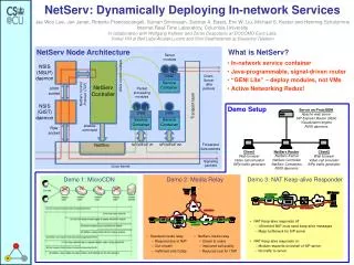
8600G 8600A 3/11 3/2 3/5 3/1 MLT1 8600C MLT1 3/12 3/3 4/30 3/30 3/22 3/29 3/21 IST IST 3/29 4/20 3/30 4/1 4/30 Tester Tester Tester Tester 4/29 4/11 3/3 SMLT 3/1 4/29 4/12 3/2 MLT30 8600D 8600B VLAN 10 8600G 8600A 3/11 3/2 3/5 3/1 MLT1 8600C 3/12 3/3 4/30 3/30 3/22 3/29 3/21 IST MLT 1 3/29 4/20 3/30 4/1 4/30 4/29 4/11 3/3 SMLT 3/1 4/29 4/12 3/2 8600D 8600B SPBM – L2VSNWhat does it solve? • Inception: • Target: I-SID 10 Core has to do MAC learning and flooding No end-point provisioning VLAN must be provisioned on all switches, e.g. for VLAN 10, configuration of VLAN 10 is required on all switches Backbone VLANs in core running IS-IS (SPBM)– simple one time configuration IS-IS (SPBM) VLAN 10 VLAN 10 C-VLAN & I-SID mapping configured only on edge. Customer MAC learning and flooding only done on edge C-VLAN & I-SID mapping configured only on edge. Customer MAC learning and flooding only done on edge Core does not learn Customer VLAN/MAC
8600G 8600A 3/11 3/2 3/5 3/1 MLT1 8600C MLT1 3/12 3/3 4/30 3/30 3/22 3/29 3/21 10.0.2.0/24VLAN 1002 IST IST 3/29 4/20 3/30 4/1 4/30 Tester Tester Tester Tester 4/29 4/11 3/3 SMLT 3/1 4/29 4/12 3/2 MLT30 8600D 8600B 8600G 8600A 3/11 3/2 3/5 3/1 MLT1 8600C 3/12 3/3 Two Core OSPF Vlans:Vlan 921 10.0.21.0/24Vlan 922 10.0.22.0/24 4/30 Two Core OSPF Vlans:Vlan 911 10.0.11.0/24Vlan 912 10.0.12.0/24 3/30 3/22 3/29 3/21 RSMLT IST MLT 1 RSMLT RSMLT 3/29 4/20 3/30 4/1 4/30 4/29 4/11 3/3 SMLT 3/1 4/29 4/12 3/2 8600D 8600B SPBM – GRT ShortcutsWhat does it solve? • Inception: • Target: IP Subnet A – Passive or active interface IGP 10.0.2.0/24VLAN 1002 10.0.1.0/24 VLAN 1001 RSMLT + OSPF in Core IP Subnet B – IGP Protocol IP Subnet C – IGP Protocol IP Subnet D – IGP Protocol IP Subnet A – No IGP required IS-IS 10.0.1.0/24 VLAN 1001 IP Shortcuts over IS-IS Backbone VLANs in core running IS-IS simple one time configuration IP Subnet B– No IGP required
8600G 8600A 3/11 3/2 3/5 3/1 MLT1 8600C MLT1 3/12 3/3 4/30 3/30 3/22 3/29 3/21 IST IST 3/29 4/20 3/30 4/1 4/30 Tester Tester Tester Tester 4/29 4/11 3/3 SMLT 3/1 4/29 4/12 3/2 MLT30 8600D 8600B 8600A 8600G 3/11 3/2 3/5 3/1 MLT1 8600C 3/12 3/3 Two Core OSPF Vlans:Vlan 921 10.0.21.0/24Vlan 922 10.0.22.0/24 4/30 Two Core OSPF Vlans:Vlan 911 10.0.11.0/24Vlan 912 10.0.12.0/24 3/30 3/22 3/29 3/21 RSMLT IST MLT 1 RSMLT RSMLT 3/29 4/20 3/30 4/1 4/30 4/29 4/11 3/3 SMLT 3/1 4/29 4/12 3/2 8600D 8600B SPBM – L3VSNWhat does it solve? VRF Configuration, IGP configuration, iBGP peering, MPBGP, Route Targets, Router Distinguishers • Inception: • Target: VRF Configuration, IGP configuration, iBGP peering, MPBGP, Route Targets, Router Distinguishers VLAN 1001 10.0.2.0/24VLAN 1002 I-SID 101 IP Subnet C – IGP Protocol IP Subnet B – IGP Protocol IS-IS (SPBM) VLAN 101 10.0.101.0/24 VRF Configuration & I-SID mapping VRF Configuration & I-SID mapping VLAN 102 Backbone VLANs in core running IS-IS (SPBM)– simple one time configuration
SPBM • SPBM (Shortest Path Bridging – MAC, previously known as SPBB) provides additional values which capitalize on IEEE 802.1ah (PBB) capabilities. • SPBM reuses the IEEE 802.1ah (PBB) data plane which does not require that the Backbone Core Bridges (BCB) learn encapsulated client addresses (C-MAC). • Individual MAC frames (unicast traffic) from an Ethernet attached device that are received at the SPBM edge are encapsulated in a (MAC-in-MAC) IEEE 802.1ah header and then traverse the network unchanged until they are stripped of the encapsulation as they egress back to the non participating attached network at the far side of the participating network
SPB Shortest Path Bridging • The SPB service is made possible by adding a new header with an I-SID, a BVLAN with source and destination B-MAC addresses • The B-VLAN is a 802.1Q VLAN used in the core used to transport the PBB EVPNs • the p-bits contained within the 802.1Q VLAN header provide QoS capabilities
Shortest Path Bridging • The backbone simply provides forwarding between backbone switches where the unicast-fib is populated by B-MAC • Each bridge has one unique MAC address known as the B-MAC and advertised by IS-IS as the SYS-ID • On the ERS 8600/8800, this is the system-id which can be configured or left as-is • Good idea to change the system-id to easily identify switches in the IS-IS forwarding table ERS-2> show isis system-id ================================================================================ ISIS System-Id ================================================================================ SYSTEM-ID -------------------------------------------------------------------------------- 00be.b000.0002 ERS-1> show isisspbmunicast-fib vlan 40 ================================================================================ SPBM UNICAST FIB ENTRY INFO ================================================================================ DESTINATION BVLAN SYSID HOST-NAME OUTGOING COST ADDRESS INTERFACE -------------------------------------------------------------------------------- 00:be:b0:00:00:02 40 00be.b000.0002 ERS-2 2/2 10 00:be:b0:00:00:03 40 00be.b000.0003 ERS-3 2/2 20 00:be:b1:00:00:03 40 00be.b000.0003 ERS-3 2/2 20 00:be:b0:00:00:04 40 00be.b000.0004 ERS-4 2/2 20
SPBM I-SID L2 VSN • The I-SID is the ‘Instance Service Identifier’ made up of a 24-bit field providing over 16 million possible VSN-id’s. The I-SID is used to identify the VSN service. • Each I-SID is assigned a unique identifier (valid range 1 to 16777215) • For L2 VSN, I-SID assigned at VLAN level ERS-1# show config module vlan # # VLAN CONFIGURATION - PHASE I # vlan 1000 create byport 1 name "VSN-Blue" vlan 1000 i-sid 1000 ERS-1# show isisspbmi-sid all ================================================================================ SPBM ISID INFO ================================================================================ ISID SOURCE NAME VLAN SYSID TYPE -------------------------------------------------------------------------------- 1000 0.00.01 40 00be.b000.0001 config 1000 0.00.02 40 00be.b000.0002 discover 1000 0.00.03 40 00be.b000.0003 discover 1000 0.00.04 40 00be.b000.0004 discover
SPBM I-SID L3 VSN • For L3 VSN, I-SID assigned at VRF level ERS-1# show config module ip # # VRF CONFIGURATION # ipvrf green create id 1 # # CIRCUITLESS IP INTERFACE CONFIGURATION - VRF # ipvrf green circuitless-ip-int 2 create 10.1.1.1/ 255.255.255.255 # # IPVPN CONFIGURATION # ipvrf green ipvpn create ipvrf green ipvpni-sid 1002 ipvrf green ipvpn enable # # IP REDISTRIBUTION CONFIGURATION - VRF # ipvrf green isis redistribute direct create ipvrf green isis redistribute direct metric 1 ipvrf green isis redistribute direct enable ERS-1# show isisspbmip-unicast-fib all ******************************************************************************* Command Execution Time: WED DEC 01 09:39:04 2010 EST ******************************************************************************* ================================================================================ SPBM IP-UNICAST FIB ENTRY INFO ================================================================================ OUTGOING SPBM PREFIX VRF ISID Destination NH BEB VLAN INTERFACE COST COST -------------------------------------------------------------------------------- green 1002 10.5.1.3/32 ERS-3 40 2/2 20 1 green 1002 10.5.1.3/32 ERS-3 41 2/2 20 1 green 1002 10.5.102.0/24 ERS-3 40 2/2 20 1 green 1002 10.5.102.0/24 ERS-3 41 2/2 20 1
SPBM Unicast • Unicast Ethernet frames in SPBM are encapsulated with a destination B-MAC and a source B-MAC and a backbone VLAN ID • The backbone source address is a B-MAC associated with the ingress 802.1aq bridge • The backbone destination address is a B-MAC associated with the egress 802.1aq bridge • B-VID – 802.1aq specification allows for tagged or untagged frames • ERS 8600/8800 uses VLAN tagging • The FDB entries map destination B-MAC, B-VID to an outgoing interface based on IS-IS database and computations
SPBM IS-IS LSDB Details 1 of 2 ERS-1# show isislsdbsysid 00be.b000.0003 detail =================================================== ISIS LSDB (DETAIL) =================================================== --------------------------------------------------- Level-1 LspID: 00be.b000.0003.00-00 SeqNum: 0x000004d9 Lifetime: 537 Chksum: 0xd4df PDU Length: 237 Host_name: ERS-3 Attributes: IS-Type 1 TLV:1 Area Addresses: 1 10.0001 TLV:3 End System Neighbors: Metric: 0 00beb0000003 (ERS-3) TLV:22 Extended IS reachability: Adjacencies: 2 TE Neighbors: 2 00be.b000.0002.00 (ERS-2) Metric:10 SPBM Sub TLV: Instance: 0 Attr: 0 Metric: 10 00be.b000.0004.00 (ERS-4) Metric:10 SPBM Sub TLV: Instance: 0 Attr: 0 Metric: 10 TLV:129 Protocol Supported: SPBM TLV:180 SPBM INSTANCE: Instance: 0 Attr: 0 OUI: 00-00-03
SPBM IS-IS LSDB Details 2 of 2 TLV:184 SPBM IPVPN Reachability: Vrf ISID:1002 Metric:1 Prefix Length:32 IP Address: 10.5.1.3 Vrf ISID:1002 Metric:1 Prefix Length:24 IP Address: 10.5.102.0 TLV:183 ISID: Instance: 0 Metric: 0 B-MAC: 00-be-b0-00-00-03 BVID:40 Number of ISID's:2 1000(Both),1001(Both) Instance: 0 Metric: 0 B-MAC: 00-be-b0-00-00-03 BVID:41 Number of ISID's:2 1000(Both),1001(Both) Instance: 0 Metric: 0 B-MAC: 00-be-b1-00-00-03 BVID:40 Number of ISID's:1 16777215(None) IP Networks Received Via I-SID 1002 B-VID 40 B-VID 41 Virtual B-MAC
SPBM IS-IS Type Length Value (TLV) Details • Some important TLV details can be viewed by issuing the following commands: • Area address – type 1 • show isislsdbtlv 1 detail • End System Neighbors – type 3 • show isislsdbtlv 3 detail • Extended IS Reachability Information – type 22 • show isislsdbtlv 22 detail • Protocols Supported – type 129 • show isislsdbtlv 129 detail • Extended IP Reachability – type 135 (SPB Native IP Shortcuts) • show isislsdbtlv 135 detail • Extended Reachability TLV – type 180 • show isislsdbtlv 180 detail • SPBM IP Reachability TLV – type 184 • show isislsdbtlv 184 detail
SPBM Unknown Traffic • SPBM uses source specific multicast trees • SPBM (S,G) forms the destination B-MAC by concatenating the 20 bit SPB unique nickname and the 24-bit I-SID • Broadcast, multicast and unknown unicast frames arriving on a UNI port are: • Encapsulated using this destination B-MAC address for the I-SID defined • The destination B-MAC uniquely identifies the encapsulating node or root of the multicast distribution tree
I-SID in Hexadecimal NICK-NAME & “3” SPBM Unknown Traffic • Example : ERS-1 Nickname = 0.00.01 , I-SID = 1000 (0x3e8) Multicast Address = 03:00:01:00:03:e8 ERS-1# show isisspbm multicast-fib i-sid 1000 ================================================================================ SPBM MULTICAST FIB ENTRY INFO ================================================================================ MCAST DA ISID BVLAN SYSID HOST-NAME OUTGOING-INTERFACES -------------------------------------------------------------------------------- 03:00:01:00:03:e8 1000 40 00be.b000.0001 ERS-1 2/2 03:00:01:00:03:e8 1000 41 00be.b000.0001 ERS-1 2/2 ERS-1# show isisspbm nick-name ================================================================================ ISIS SPBM NICK-NAME ================================================================================ LSP ID LIFETIME NICK-NAME HOST-NAME -------------------------------------------------------------------------------- 00be.b000.0001.00-00 334 0.00.01 ERS-1 00be.b000.0002.00-00 576 0.00.02 ERS-2 00be.b000.0003.00-00 828 0.00.03 ERS-3 00be.b000.0004.00-00 379 0.00.04 ERS-4
86 - 20 2/11 2/12 86 - 10 86 - 30 2/11 2/12 2/10 2/10 2/1 2/1 SPBM Unknown Traffic – Constrained Multicast • Per Node multicast tree for each I-SID • Intermediate nodes only install multicast MAC address when they are in the path 86-20:5# show isisspbm multicast-fib ================================================================ SPBM MULTICAST FIB ENTRY INFO ================================================================ MCAST DA ISID BVLAN SYSID HOST-NAME OUTGOING-F ----------------------------------------------------------------------------------- All links active – No traffic going through 86-20 86-20:5# # show isisspbm multicast-fib ================================================================ SPBM MULTICAST FIB ENTRY INFO ================================================================ MCAST DA ISID BVLAN SYSID HOST-NAME OUTGOING-IF ---------------------------------------------------------------------------------------------------------------- 03:00:10:00:00:64 100 10 0080.2d35.93df 86-10 2/12 03:00:10:00:00:c8 101 10 0080.2d35.93df 86-10 2/12 03:00:30:00:00:64 100 10 00e0.7b84.57df 86-30 2/11 03:00:30:00:00:c8 101 10 00e0.7b84.57df 86-30 2/11 Link failure between 86-10 / 86-30 – All traffic going through 86-20
Intermediate System to Intermediate System (IS-IS) • IS-IS is an interior gateway protocol (IGP) that was developed for the International Organization for Standardization (ISO DP 10589) • Defined in ISO/IEC 10589:2002 as international standard within Open Systems Interconnection (OSI) • IETF republished in RFC 1142 • IS-IS is a link-state routing protocol • Uses the Dijkstra algorithm for computing the best path through network in common with OSPF • SPBM uses IS-IS at layer 2, it does not need IP addressing configured
Intermediate System to Intermediate System (IS-IS) • IS-IS differs from OSPF in the way areas are defined and routed between • Unlike OSPF, IS-IS is designed to work in one flat area • IS-IS routers are designated as being Level 1 (intra-area), Level 2 (inter-area), or Level 1-2 (both) • Note: We only support Level 1 at this time • Forwarding information is exchanged between Level 1 routers • Level 2 routers only exchange information with other Level 2 or Level 1-2 routers • Does not required area 0 like OSPF • A IS-IS router is only ever part of a single area • IS-IS is protocol agnostic whereas OSPF was designed for IPv4
Intermediate System to Intermediate System (IS-IS) Example: ERS-1 connected to ERS-2 via port 2/2 ERS-1# show config module isis # # ISIS CONFIGURATION # isis is-type l1 isis system-id 00be.b000.0001 isis manual-area add 10.0001 isis enable ERS-1# show isis interface ================================================================================ ISIS Interfaces ================================================================================ IFIDX TYPE LEVEL OP-STATE ADM-STATE ADJ UP-ADJ SPBM-L1-METRIC -------------------------------------------------------------------------------- Port2/2 pt-pt Level 1 UP UP 1 1 10 ERS-1# show isis adjacencies ================================================================================ ISIS Adjacencies ================================================================================ INTERFACE L STATE UPTIME PRI HOLDTIME SYSID HOST-NAME -------------------------------------------------------------------------------- Port2/2 1 UP 01:49:31 127 18 00be.b000.0002 ERS-2 ERS-1# show isis info =========================================== ISIS General Info =========================================== AdminState : enabled RouterType : Level 1 System ID : 00be.b000.0001 Max LSP Gen Interval : 900 Min LSP Gen Interval : 30 Metric : wide Overload-on-startup : 20 Overload : false Csnp Interval : 10 PSNP Interval : 2 Rxmt LSP Interval : 5 spf-delay : 100 Router Name : ERS-1 ip source-address : Num of Interfaces : 1 Num of Area Addresses : 1
IEEE 802.1ag Connectivity Fault Management • Connectivity Fault Management (CFM) offers loopbacks and link trace for troubleshooting, and continuity checks for fast fault detection. • CFM allows operators, service providers and customers to verify the connectivity that they provide or utilize and the connectivity that is provided to them. This is accomplished through: • Periodic messaging between endpoints within a domain for the purpose of fault identification. (CCM) • Loopback (aka L2 ping) messaging to an intermediate or endpoint within a domain for the purpose of fault verification. (LBM) • Linktrace (aka L2 trace) messaging to a maintenance endpoint with intermediate points responding to indicate the path of the traffic within a domain for the purpose of fault isolation. (LTM)
ETHERNET ACCESS ETHERNET ACCESS CUSTOMER CORE CUSTOMER Customer level (7) Provider level (3) Provider level (1) Provider level IEEE 802.1ag Connectivity Fault Management • Maintenance Domain – MD • MD are management space on a network, typically owned and operated by a single entity MD are configured with Names and Levels, where the eight levels range from 0 to 7. • Hierarchal relationship exists between domains based on levels.
IEEE 802.1ag Connectivity Fault Management • Maintenance Association • Maintenance Association (MA) is “A set of MEPs, all of which are configured with the same MAID (Maintenance Association Identifier) and MD Level, each of which is configured with a MEPID unique within that MAID and MD Level, and all of which are configured with the complete list of MEPIDs” • Maintenance End Point • Maintenance End Point (MEP), are Points at the edge of the domain, define the boundary for the domain. A MEP sends and receives CFM frames through the relay function, drops all CFM frames of its level or lower that come from the wire side • Maintenance Intermediate Point • Maintenance Intermediate Point (MIP), are Points internal to a domain, not at the boundary. CFM frames received from MEPs and other MIPs are cataloged and forwarded, All CFM frames at a lower level are stopped and dropped. MIPs are passive points and respond only when triggered by CFM trace route and loop-back messages • Example: Maintenance Domain = Ottawa, Maintenance Association = 40 (selected 40 to coincide with B-VLAN 40, MEP = 1 (1 associated with switch ERS-1; can be same or unique per switch)
IEEE 802.1ag Connectivity Fault Management ERS-1# show config module cfm # # MAINTENANCE-DOMAIN CONFIGURATION # cfmmd "Ottawa" create index 1 # # MAINTENANCE-ASSOCIATION CONFIGURATION # cfmmd "Ottawa" ma "40" create index 1 cfmmd "Ottawa" ma "41" create index 2 # # MAINTENANCE-ENDPOINT CONFIGURATION # cfmmd "Ottawa" ma "40" mep1 create state enable cfmmd "Ottawa" ma "41" mep1 create state enable # # VLAN NODAL MEP/MIP CONFIGURATION # vlan 40 add-nodal-mep Ottawa.40.1 vlan 41 add-nodal-mep Ottawa.41.1 ERS-1# show cfmmep info ================================================================================ Maintenance Endpoint Config ================================================================================ DOMAIN ASSOCIATION MEP ADMIN NAME NAME ID -------------------------------------------------------------------------------- Ottawa 40 1 enable Ottawa 41 1 enable Total number of MEP entries: 2. ================================================================================ Maintenance Endpoint Service ================================================================================ DOMAIN_NAME ASSN_NAME MEP_ID TYPE SERVICE_DESCRIPTION -------------------------------------------------------------------------------- Ottawa 40 1 nodal Vlan 40, Level 4 Ottawa 41 1 nodal Vlan 41, Level 4
IEEE 802.1ag Connectivity Fault Management • ERS-1# l2ping 40.ERS-3 (B-VLAN.Remote Switch Name) • Please wait for l2ping to complete or press any key to abort • ----00:be:b0:00:00:03 L2 PING Statistics---- 0(68) bytes of data • 1 packets transmitted, 1 packets received, 0.00% packet loss • round-trip (us) min/max/ave/stdv = 490/490/490.00/ 0.00 • ERS-1# l2traceroute 40.ERS-3 (B-VLAN.Remote Switch Name) • Please wait for l2traceroute to complete or press any key to abort • l2traceroute to ERS-3 (00:be:b0:00:00:03), vlan 40 • 0 ERS-1 (00:be:b0:00:00:01) • 1 ERS-3 (00:be:b0:00:00:03) • ERS-1:5# l2tracetree 40.1000 (B-VLAN.I-SID) • Please wait for l2tracetree to complete or press any key to abort • l2tracetree to 03:00:01:00:03:e8, vlan 40 i-sid 1000 nickname 0.00.01 hops 64 • 1 ERS-1 00:be:b0:00:00:01 -> ERS-2 00:be:b0:00:00:02
SPBM Split Multilink Trunking (SMLT) NNI • IS-IS for SPB currently only supports pt-to-pt adjacencies • Only one link or one MLT is supported between a pair of ERS 8600/8800 switches • Single port Ethernet • MLT (1 to 8 ports) considered as a pt-to-pt link
SPBM SMLT NNI Triangle Configure each interface as IS-IS pt-to-pt. If multiple links are required, configure MLT first then configure IS-IS on the MLT Square MLT is local on lower Switch. IS-IS is configured on interfaces (port on upper switch, MLT on lower switch.
SPBM SMLT NNI IS-IS should be configured on only one of the links between B and D Square Configure each interface as IS-IS pt-to-pt. If multiple links are required, configure MLT first then IS-IS
SPBM SMLT NNI Configure each interface as IS-IS pt-to-pt IS-IS should be configured on only one of the links between B and D
SPBM Hashing • MLT hashing for ingress UNI traffic: • IP traffic is hashed based on Source_IP, Destination_IP and TCP/UDP port number • Non-IP traffic is hashed based on Source_CMAC and Destination_CMAC • MLT hashing for ingress NNI (encapsulated) traffic: • IP traffic is hashed based on Source_IP, Destination_IP • Non-IP traffic is hashed based on Source_CMAC and Destination_CMAC NNI UNI UNI NNI MLT MLT
SPBM Equal Cost Multi Tree • Equal Cost Multi Tree (ECMT) in 802.1aq allows for two or more equal cost paths • I-SID hashing: • Odd I-SIDs take Primary B-VID • Even I-SIDs take Secondary B-VID B-VID 40 Primary I-SID 100 I-SID 101 B-VID 50 Secondary
SPBM Supported Services • SPB L2 VSN • Software Support: ERS 8K 7.1, VSP9K 3.2, VSP7K 10.2 • L2 Services over IS-IS • I-SID to VLAN mapping • IP Shortcuts • Software Support: ERS 8K 7.1, VSP 9K 3.2 • Using Global Routing Table (over native IS-IS) • No I-SID mapping • SPB L3 VSN • Software Support: ERS 8K 7.1, VSP 9K 3.2 • L3 VRF over IS-IS • I-SID to VRF mapping • Inter-ISID Routing • Software Support: ERS 8K 7.1, VSP 9K 3.2 • Routing between two or more SPB L2 VSNs • IP Multicast • Software Support: ERS 8K 7.2 • Dynamic I-SID assignment based on S,G, and I-SID
SPBM Supported ServicesSPB L2 VSN • An SPB L2 VSN is simply made up of a number of Backbone Edge Bridges used to terminate Layer 2 VSN • Only BEB bridges are aware of any L2 VSNs and C-MACs • BCBs only learn B-MACs • An I-SID is configured on the BEB for each VLAN • All VLANs in the network that share the same I-SID will be able to participate in the same VSN
SPBM Supported ServicesSPB L2 VSN—Continued • TLVs are used to identify SPBM instance, link metric’s, and B-VLAN, B-MAC, number of I-SID’s • Show isis lsdb detail • Show isis lsdb tlv 183 detail
SPBM Supported ServicesIP Shortcuts • No I-SIDS used • IP forwarding over IS-IS • ECMP Supported • IP ECMP must be enabled • Need to enable IS-IS redistribution (direct|rip|ospf|static|BGP) • IS-IS IP distributed without IS-IS redistribution enable • TLV 135 (Extended IP Reachability) is used between IS-IS peers
SPBM Supported ServicesSPB L3 VSN • L3 VRF over IS-IS • A SPB L3 VSN topology is very similar to a SPB L2 VSN topology with the exception that a Backbone Service Instance Identifier (I-SID) will be assigned at the Virtual Router (VRF) level instead of at a VLAN level • All VRFs in the network that share the same I-SID will be able to participate in the same VPN • The SPBM IPVPN Reachability TLV 184 is used to distribute IPVPN reachability between IS-IS peers
SPBM Supported ServicesSPB L3 VSN—Continued • Note, any routing protocol can be used in the redistribution policy
SPBM Supported ServicesInterISID Routing • Inter-ISID allows route leaking between two or more VLANs on local BEB switches • Inter-ISID is typically enabled on a core switch as shown above to route between VLANs from two or more BEB switches • Can be done via VRF as shown above or via IP Shortcuts
SPBMConfiguration • Core configuration – Basic Setup • Enable SPBM • Create B-VLAN(s) • Create two (primary and secondary for ECMT) • Add SPBM instance (a number from 1 to 100) • Add Nick-name (x.xx.xx) • Add B-VLAN(s) • Add all B-VLANs and set primary B-VLAN • On a SMLT Cluster • A Virtual B-MAC must be configured plus IST peering using neighbor System ID • The Virtual B-MAC must be the same on both cluster switches • Enable IS-IS on interface level • Individual port or MLT • If MLT, create MLT first then enable IS-IS on MLT