Download
1 / 30
300 likes | 303 Views
The Queen's Hyperloop Design Team, comprised of undergraduate engineering and business students, presents their preliminary design submission for the pod. This includes an introduction, subsystem design, safety factors, consumption and cost analysis, and a conclusion.

E N D
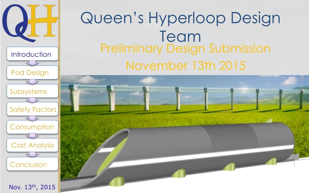
Queen’s Hyperloop Design Team Introduction Preliminary Design Submission November 13th 2015 November 13, 2015 Pod Design Subsystems Safety Factors Consumption Cost Analysis Conclusion Nov. 13th, 2015
Team Introduction The Queen’s Hyperloop Design Team is a group of undergraduate engineering and business students at Queen’s University in Canada. Students in engineering range from Civil engineering to Mechanical and Chemical Engineering. From their respective programs, each member of the team is able to bring their strengths and skills to form a dedicated and hardworking design team. Through the use of open discussion and scheduled meetings the team is able to keep deliverables on track and up to the standards of each team member. The design has been worked on substantially to ensure key preliminary design aspects were all covered. The team intends to compete in all aspects of the competition, including travelling to and presenting at the design competition, building the pod (including all subsystems) and to transport it for testing. Introduction Pod Design Subsystems Safety Factors Consumption Cost Analysis Conclusion Nov. 13th, 2015
Underlying Assumptions • All the air hitting the front of the vehicle is directed into the air system, the mass flow through the system is dictated by the vehicle speed and frontal area • Model design speed is 100 km/hr • Model design weight is 500 lbs • Air for the air bearings is stored on board in a pressure vessel • The pressure of the air for the air bearings is constant for all vehicle speeds and weights • The flow rate of air for the air bearings scales with the weight of the vehicle • The model is moving about 10x slower than the real vehicle, so the mass of air entering the model is about 10x less, and the model therefore does not ingest enough air for the on board compressor system to supply the air bearings • This is a scaling problem related to the reduced model speed of the half scale model that does not occur at the high speeds of the real vehicle Introduction Pod Design Subsystems Safety Factors Consumption Cost Analysis Conclusion Nov. 13th, 2015
Core Pod Specifications • Facts & Figures for 1/2 scale pod: • Pod diameter: 0.75 m • Pod Length: 4 m • Roughly circular cross-section • Passenger compartment 1.5 m long • 1m long entrance hatch • Pusher cart interface plate mounted to rear • Mainly made of aluminum, fiberglass, and carbon fiber • Estimated weight breakdown: • Thermo-Compressor system & Piping: 40 lbs • Shell exterior: 50 lbs • Pod Structure: 100 lbs • Electronics, Sensors, & wiring: 20 lbs • Battery: 100 lbs • Halbach arrays: 80 lbs • Guiding & Stability systems: 40 lbs • Onboard Air tank: 50 lbs • Primary Breaking- Wheel, and disc brake: 30 lbs • Secondary Breaking: 20lbs • Total estimated weight: 530 lbs (excl. passenger & compartment furnishing) Introduction Pod Design Subsystems Safety Factors Consumption Cost Analysis Conclusion Nov. 13th, 2015
Pod Model Introduction Pod Design Subsystems Safety Factors Consumption • The exterior design will feature a contrasting colour and texture scheme to increase the visual appeal and passenger experience. With graphic layout TBD. • Coated and painted fiberglass will comprise the outer shell while polished aluminium will be used for the cylindrical Halbach array housings, frontal intake, shark fin, and rear pusher cart interface plate. • Fiberglass was chosen over the primary contenders of carbon fiber and aluminum due to a lower price, sufficient material strengths, and ease of manufacturing. Cost Analysis Conclusion Nov. 13th, 2015
Pod Model Introduction Pod Design Subsystems Safety Factors Consumption Cost Analysis • passenger hatch will have a brushed aluminum texture and anodized colour to differentiate and allow for easy identification of the entrance and • Serve as indicator for rescue workers in case of an emergency.The lifting magnet system will be housed in the eight cylindrical units shown. Conclusion Nov. 13th, 2015
Pod Schematic Introduction Click to add text Pod Design Subsystems Safety Factors Consumption Cost Analysis Conclusion Nov. 13th, 2015
Aerodynamic Design Approach Introduction Pod Design Image from Hyperloop Alpha document • Assume the vehicle frontal area is half the tunnel cross section • The two main sources of drag on the vehicle are aerodynamic drag and wheel friction from any guide or support wheels touching the tunnel floor/walls. • Treating the vehicle as a circular cylinder facing end-on into the flow, the drag force at cruise is ~1 N. • Pneumatic rubber tires supported by ball bearings rolling on concrete produce a rolling resistance of about 1.5% of the normal force • Conservatively assuming that tires would only assume 50% of the vehicle weight (other levitation methods should support the entire weight, but for redundancy assume 50% of weight is on wheels), the wheel friction is ~16 N • The thrust required at cruise is equal to the sum of these two resisting forces • Given the required thrust and the available massflow, an exhaust velocity of 230 m/s (~Mach 0.7) is required to drive the vehicle Subsystems Safety Factors Consumption Cost Analysis Conclusion Nov. 13th, 2015
Aerodynamic Design • Due to drag being ~1 N, it is unnecessary to alter the design of the pod too much to limit drag . A small lip at the front of the pod will provide minimal lift at the top speed projected for the half scale pod, this will of course change at full scale where the pod would act as a lifting wing and decrease the load on the levitation systems at high speed. • The air hitting the front of the pod will enter into a compressor and ejected out of the air bearings. For the half scale model an additional air compressor tank will be in the pod to adjust for insufficient air mass flow rates from frontal ingestion. Introduction Pod Design Subsystems • side mounted air bearings seen on the right will be replaced by downwards Halbach arrays in our model. • The landing gear wheels will protrude from the bottom of the pod because drag would be negligible • to simplify construction, a retractable system would be implemented in a full scale pod. Safety Factors Consumption Cost Analysis Conclusion Picture of streamline simulation from Ansys. Nov. 13th, 2015
Exterior Design • Balancing the visual appeal through the exterior styling with aerodynamic and manufacturing considerations was one of main challenges. • decided to use a simple cylinder as the base shape for the pod because it would significantly reduce manufacturing cost and aerodynamic complexity. • negatively impact the pods potential as a lifting body, however because the half scale pod does not travel at high speeds this would be negligible effect. Introduction Pod Design Subsystems Safety Factors Frontal, Bottom, and Rear views of the Pod exterior Consumption • Two sets of wheels not shown will protrude from underneath the pod between the 1st & 2nd, and 3rd & 4th arrays. This will provide support during low speed movement. Cost Analysis Conclusion Nov. 13th, 2015
Thermo-Compressor System • An exhaust nozzle of diameter 30cm and a pressure ratio across the compressor system of 1.33 will be required. The power required to drive the compressor system is 3.2 kW • Centrifugal flow compressor from commercially available off-the-shelf components for half scale model. Axial compressors likely for full scale. • This pressure rise can be achieved using a pair of commercial vacuum cleaner blowers in series (PR ~ 1.44). These compressors are designed to operate at STP, so to match the flow coefficient (ie: compressor flow angles) at the low tunnel pressure, two blower systems should be used in parallel, for a total of 4 blowers (2x2) • The total weight of this subsystem is about 40 lbs. This includes the four blowers, batteries to supply those blowers, and the ducting to bring the air from the intake to the blowers, and from the blowers to the exhaust • Primary acceleration will be from provided pusher cart • Rear air nozzle for backup acceleration, can be supplied • from thermo-compressors or onboard compressed air tank Introduction Pod Design Subsystems Safety Factors Consumption Cost Analysis Conclusion Nov. 13th, 2015
Levitation Systems Overview Introduction The levitation is divided into three main components, the magnetic guiding system, air bearing system and the Halbach array system A Halbach array is a configuration of alternating attractive and repulsive permanent magnets , and produce force by inducing a current in the receiving aluminum, creating a magnetic force which repels the magnet . The magnetic levitation system will be used to levitate off the aluminum sub-track and as a guiding system off the central portion of the track Implements similar technology as the “ArxPax” Hover board. [1] Utilize neodymium magnets as the main source to provide the lifting magnetic force. These permanent magnets will be placed on a cone shaped disc which will rotate perpendicular and overtop the aluminum sub-track at a very high velocity (RPM) to generate the required magnetic field. Of special note isthat the magneticguiding system isonlyfeasiblefortrack design “C”, as induced magnetic effects in the aluminum central beam in designs “A” and “B” would reduce effectiveness. Pod Design Subsystems Safety Factors Consumption Cost Analysis Conclusion
Air Bearings • Air will be supplied by air compressor tank • Form inspired by solutions available through “NewWay” Air Bearings • Rectilinear bearing shape efficient for fully linear motion than circular bearing • Note that the design was changed after it was revealed that the smooth surface required for air bearings would be on a central track. • Mass flow rate of air through porous media requires careful consideration • Flow rate is cubic function of gap size, per “NewWay” Air Bearing Application & Design Guide: • For a 2-inch diameter air bearing carrying 75lbs of load to generate 200 micro inches of lift, it will require 4 cubic feet per hour of supplied air. • This same 2-inch diameter air bearing, carrying the same load, would require an air supply of 64 cubic feet per hour. Introduction Pod Design Subsystems Safety Factors Consumption Cost Analysis Conclusion Nov. 13th, 2015
Air Bearings - Continued • Based upon industrial air bearings and “flipped air hockey table” concept • Rectangular block with perforated flat bottom surface • Feed air from Thermo-compressor system at full speed, • Feed air from onboard air tank at low speeds and for half scale testing • Dimensions for main block (LxWxH): 20cm x 10cm x 5cm • Options for suspension system technology: • Pneumatic (exhibit A) • Spring (Exhibit B) Introduction Pod Design Subsystems Safety Factors Consumption Cost Analysis Conclusion Revised air bearing block design, with spring suspension Air Hockey Table with micro perforations Nov. 13th, 2015
Exhibit A Introduction Pod Design Subsystems Safety Factors Consumption • Exhibit B Cost Analysis Conclusion Nov. 13th, 2015
Air Bearings - Continued • Decided to modify placement and design as decision to integrate air bearings inside pod overtop rail flange was made after updated tube-specs were released. • Final design proposed below Introduction Pod Design Subsystems Safety Factors Consumption • Exhibit B Cost Analysis Conclusion Nov. 13th, 2015
Hallbach Levitation Arrays • A hallbach magnetic motor is created by arranging permanent magnets in an alternating pattern. • These alternating magnetic paterns are arranges in rows of rings in a hallbach motor. • When the motor is set to spin at very high speeds and placed over aluminum, the motors induce eddy currents in the metal. • The eddy currents create their own fields which oppose the magnetic field and create an upwards repulsive force on the motors. Introduction Pod Design Subsystems Safety Factors The following picture is one of the Halbach array motors that will be utilizing rows of alternating magnets. There will be 8 arrays in total mounted in 4 pairs spinning in opposing directions. The team has not yet concluded on the number and sizing of individual magnets for each circular array. This will be done preceding the final design. Consumption Cost Analysis Conclusion Nov. 13th, 2015
Guiding and Stability System • Comprised of guiding wheel sets and magnetic array pairs • Extra redundancy in case of failures and emergencies with additional magnetic guiding system • Miniaturized versions of lifting units will be used • Computer controlled input with feedback from proximity sensors Introduction Pod Design Subsystems Safety Factors Consumption Cost Analysis Baseboard mounting plate for guide-wheels and magnet stability system Conclusion Attachment bolt Nov. 13th, 2015
Wheeled Guiding system • On the bottom of the baseboard shown to the left there are attachments to add the wheel pairs. • Wheels will be made out of standard solid rubber, commonly found from suppliers like Mcmaster-Carr • Wheels are oriented parallel and perpendicular tothe bottomof the top flange • 2 sets in total located near the front and back ofthe pod Introduction Pod Design Subsystems Safety Factors Consumption Cost Analysis Conclusion Nov. 13th, 2015
Magnetic Guiding System Introduction To right of slide is a conceptual sketch of the magnetic proposed guiding system. Side view shows the cone shaped disk that will house the magnets. large rectangle behind the cone shape is the motor that will be attached to the rotating disk. Same technology will be used for the magnetic levitations system. magnets will be able to produce a repulsive force of 556KN. It must be noted that the a force of 556KN for the guiding wheels is extremely high and will be adjusted in the coming weeks. total of 4 guiding magnets on pod, two on left side and two on right Magnets will be placed close to the front of the pod and the back of the pod. Dimensions of guiding system is the same as the previous diagram shown for levitation. Pod Design Subsystems Safety Factors Consumption Cost Analysis Conclusion Nov. 13th, 2015
Support Wheels & Primary Braking System The low speed wheel system comprises of two pairs of wheels located underneath the front and rear section of the pod between the levitating magnet units. They will rest on the concrete surface between the track and aluminum subtrack, and because surface is essentially smooth no suspension system will be needed. The same wheels that will be used as support during low speed operation will have attached standard ATV disk brakes to each . This allows the option for better control at low speeds and smoother braking for passenger comfort as well as an additional braking option in case of an emergency. These brakes alone can stop the entire pod (240kg) from 100 km/h within 50 m. Additional system will be for redundancy. Strengthened ATV or golf cart brakes will be used as the pod has similar vehicle weights. The main difference would be that the wheels would be mounted independently and not connected through any axle. This is to increase the volume available for the passenger compartment as well as decreasing weight. Introduction Pod Design Subsystems Safety Factors Consumption Cost Analysis Conclusion Nov. 13th, 2015
Secondary Braking System • Brake pads will be attached to a pneumatic piston • Piston arm will be attached to a swing arm that will allow it to extend outward to the sides of the tube • Electromagnetic system and air bearings will halt, allowing the weight of the pod to provide sufficient braking • One "arm" in each corner of pod • ~3m apart • 2" Bore size at 100 psi will yield ~260 lbs of Force for each arm) Introduction 0.75 m Pod Design Subsystems Safety Factors • Assumptions: • 30 m/s • 530 lbs (240.404 kg) • Pod length ~4m • Fail safe system (braking position will require no power- power is required to lift piston) Consumption Cost Analysis Pneumatic Piston Pod Shell Conclusion Brake Pads Nov. 13th, 2015
Emergency Braking • In case of emergency, both braking systems will be deployed. • To error on the side of caution, a reverse thruster (in this case just a compressed air tank) will be mounted to the front of the pod. • allows for a controlled stop without destroying or tampering with the center guide rail/ costly Halbach arrays. Introduction Pod Design Subsystems Safety Factors Consumption Cost Analysis Conclusion Nov. 13th, 2015
Sensor Array Configuration 2x Proximity sensors (Front Downwards) 2x Proximity sensors ( Rear Downwards) 2x Proximity Sensors ( Front Left and Right) 2x Proximity Sensors ( Rear Left and Right) 1x Proximity Sensor ( Front Top) 1x Proximity Sensor ( Rear Top) 2x Optical sensor (On both sides for redundancy) 2x Wi-Fi link Communications (for redundancy) 3x Thermal Sensors (Exterior Front, Bottom, and Rear) 2x Thermal Sensors (Interior – Passenger Compartment and Electronics bay to prevent overheating) 2x Pressure Sensor (Exterior Front air intake, and Rear) 1x Pressure Sensor (Interior – Passenger Compartment) Introduction Pod Design Subsystems Safety Factors Consumption Cost Analysis These will all be connected to our computer system in the electronics bay and be transmitted via the tube wireless network. Also additional sensors for monitoring voltage, current draw, and other electrical components will be integrated with the electrical system. Conclusion Nov. 13th, 2015
Safety • Hazardous Materials • Lithium Ion battery power pack can overheat and explode; sufficient cooling and ventilation will be provided. • Strong magnets can cause failure of certain sensitive electronics, especially towards pacemakers and other systems, the units will be shielded to prevent this from occurring • The cabin will be pressurized. In the case of a puncture in the pod, the pod will continue onto the next station with oxygen masks provided via a system similar to airlines. There will be an emergency supply of air on board that is sufficient to last 30 minutes (or however long it takes for the tube to pressurize to normal atmospheric conditions) • Emergency Systems • Emergency Braking (forward air bleed system from air tank) • Secondary Breaking • Emergency Capsule pressurization (interior cabin bleed from compressor & tank) • Redundant guiding and stability mechanism (Guide-wheels and guide magnets) • Fully Redundant levitation systems would be implemented in full scale in case of catastrophic failure • Always deployed wheel system for emergency power loss Introduction Pod Design Subsystems Safety Factors Consumption Cost Analysis Conclusion Nov. 13th, 2015
Power System • Power Consumptions: • 3.2 KW for Compressors • 8x 12V (1A) Halbach Array motors • Sensors and telemetry are negligible in terms of power consumption • Additional 8x 12v (20mA) magnet guiding motors • Estimated total power consumption with safety margin = 5 kW • 4 Lithium ion batteries will be connected in series. The motors will be connected in parallel to the series. The batteries required will be ~80 V and 10 Ah. • Total stored energy of approximately 3200 Wh, more than enough for testing. Introduction Pod Design Subsystems Safety Factors Consumption Cost Analysis Conclusion Nov. 13th, 2015 Example of battery pack used
Preliminary Cost Estimate Introduction The pod structure material cost is estimated to be roughly $2000 CAD. The end construction cost is predicted to be roughly $20 000 CAD. A fullsize pod constructed to our design would feature a unit cost of approximately $1 million USD, less than the original proposal. Pod Design Subsystems Safety Factors Consumption Cost Analysis Conclusion Nov. 13th, 2015
Next Steps Introduction Pod Design Subsystems Safety Factors Consumption Cost Analysis Conclusion Nov. 13th, 2015
References Pod Materials Information: Levitation: http://www.google.com/patents/US9126487 http://www.askmar.com/Magnets/Halbach%20Array%20Motor.pdf Pod Shell and Ribs Materials Prices: http://www.metalprices.com/metal/aluminum/aluminum-alloy-6061-scrap-mill-grade http://www.noahsmarine.com/Canada/2002_cdn_catalog.pdf http://www.build-on-prince.com/carbon fiber.html#sthash.1JWBVR4d.dpbs [BO] Mcmaster-Carr. mcmaster.com. [Online]. http://www.mcmaster.com/#=zslq2c Introduction Pod Design Subsystems Safety Factors Consumption Cost Analysis Conclusion Nov. 13th, 2015
Team List Team Leader: Advisors: Michael Zuo Jimmy Krawfert (PHD Advisor) Dr. Michael A. Birk Team Members: Arthur Cockfield Tarrance Kong Lizzie Williams Jean-Samuel Poirier Jonathan Brickman Katie Kirsche Introduction Pod Design Subsystems Safety Factors Consumption Cost Analysis Conclusion Nov. 13th, 2015