Download
1 / 17
170 likes | 178 Views
Electric Field Instrument (EFI) Engineering Peer Review Overview Dr. John W. Bonnell and the THEMIS EFI Team Space Sciences Laboratory University of California - Berkeley. Overview. THEMIS EFI Personnel and Organization Requirements and Specifications Top-Level Design

E N D
Electric Field Instrument (EFI) • Engineering Peer Review • Overview • Dr. John W. Bonnell and the THEMIS EFI Team • Space Sciences Laboratory • University of California - Berkeley
Overview • THEMIS EFI • Personnel and Organization • Requirements and Specifications • Top-Level Design • Design Drivers – DC Error Budget • Design Drivers – AC Error Budget • Active Design Trades
Personnel and Organization • Organizational Chart: • Prof. F. Mozer (THEMIS EFI Co-I). • Drs. J. Bonnell, G. Delory, A. Hull (Project Scientists) • P. Turin (THEMIS Lead ME) • Dr. D. Pankow (THEMIS Advising ME) • B. Donakowski (THEMIS EFI Lead ME, SPB) • R. Duck (AXB ME) • D. Schickele (Preamp, SPB ME) • S. Harris (THEMIS BEB Lead EE) • H. Richard (BEB EE) • G. Dalton (EFI GSE Mechanical) • J. Lewis, F. Harvey (THEMIS GSE) • UCBSSL Technical Staff (H. Bersch, H. Yuan, et al.)
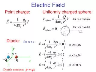
Requirements & Specs (1) • Science Requirements • EFI-1: The EFI shall determine the 2D spin plane electric field at the times of onset at 8-10 Re (4.1.1.7, 4.1.1.9). • EFI-2: The EFI shall determine the dawn-dusk electric field at 18-30 Re (4.1.1.3). • The EFI shall measure the 3D wave electric field from 1-600 Hz at the times of onset at 8-10 Re (4.1.1.11). • The EFI shall measure the waves at frequencies up to the electron cyclotron frequency that may be responsible for electron acceleration in the radiation belt (radiation belt science).
Requirements & Specs (2) • Performance Requirements • The EFI shall measure the 2D spin plane DC E-field with a time resolution of 10 s (EFI-1, EFI-2). • The EFI shall measure the 3D AC E-field from 1 Hz to 4 kHz (EFI-3). • The EFI shall measure the Spacecraft Potential with a time resolution better than the spin rate (3 s; from ESA to compute moments). • The EFI FFT Spectra range shall be 16 Hz to 4 kHz, with df/f~25% (EFI-3). • The EFI shall measure DC-coupled signals of amplitude up to 300 mV/m with 16-bit resolution. • The EFI shall measure AC-coupled signals of amplitude up to 50 mV/m with 16-bit resolution. • The EFI noise level shall be below 10-4 (mV/m)/Hz1/2. • The EFI HF RMS (log power) measurement shall cover 100-500 kHz with a minimum time resolution of the spin rate (on-board triggers). • The EFI shall achieve an accuracy better than 10% or 1 mV/m in the SC XY E-field components during times of onset (EFI-1, EFI-2).
EFI Block Diagram • A High-Input Impedance Low-Noise Voltmeter in Space sheath sensor preamp Floating ground generation BIAS USHER Bias channels GUARD VBraidCtrl VBraid BRAID Vref
Top-Level Design (1) • Diagram of THEMIS EFI Elements
Top-Level Design (2) • Description of THEMIS EFI Elements • Three-axis E-field measurement, drawing on 30 years of mechanical and electrical design heritage at UCBSSL. • Closest living relatives are Cluster, Polar and FAST, with parts heritage from CRRES (mechanical systems, BEB designs, preamp designs).
Top-Level Design (3) • Description of THEMIS EFI Elements • Radial booms: • 20.8 to 27.8 m long. • 8-cm dia., DAG-213 or Ti-N-coated spherical sensor. • 3-m fine wire to preamp enclosure. • USHER and GUARD bias surfaces integral to preamp enclosure. • BRAID bias surface of 3 to 6-m length prior to preamp (common between all 4 radial booms). • Sensor is grounded through TBD Mohm resistance when stowed, providing ESD protection and allowing for internal DC and AC functional tests. • External test/safe plug (motor,door actuator,turns click, ACTEST) to allow for deploy testing/safing and external signal injection.
Top-Level Design (4) • Description of THEMIS EFI Elements • Axial booms: • 4-m stacer with ~1-m DAG-213-coated whip stacer sensor. • Preamp mounted in-line, between stacer and sensor. • USHER and GUARD bias surfaces integral to preamp enclosure. • No BRAID bias surface. • Sensor is grounded through TBD Mohm resistance when stowed, providing ESD protection and allowing for internal DC and AC functional tests. • External test/safe plug (deploy actuator, ACTEST) to allow for deploy testing/safing and external signal injection.
Top-Level Design (5) • Performance Specification • EFI radial sensor baseline will be 41.6 m, tip-to-tip. • EFI axial sensor baseline will be ~10 m, tip-to-tip. • 16-bit resolution. • Spacecraft potential: +/- 60 V, 1.8 mV resolution, better than 46 uV/m resolution (allows ground reconstruction of E from spacecraft potential to better than 0.1 mV/m resolution). • DC-coupled E-field: +/- 300 mV/m, 9 uV/m resolution. • AC-coupled E-field: +/- 50 mV/m, 1.5 uV/m resolution. • AKR log(Power) channel: <= 70 uV/m amplitude, 100-500 kHz bandwidth.
DC Error Budget (1) • The estimated electric field along the direction between the two probes is E=(v1-v2)/2L. • Errors arise from and are mitigated by: • Errors in baseline (L). • Errors in v1 and v2; eg. (v1-v2) or each individually.
DC Error Budget (2) • Errors in baseline (L). • Fly as long of booms as possible, given resources (41.6-m baseline, ~55-m possible w/in mass resources). • Control boom length to 1%, trim deploy length to 4-cm accuracy. • Increase fine wire length to reduce boom shorting effect (observed up to 20% on Cluster; predicted 5% on THEMIS (better Lf/L)).
DC Error Budget (3) • Errors in v1 and v2; eg. (v1-v2) or each individually. • Use TI-N coating on sensors (DAG-213 on AXB) for uniform photoemission. Keep all sensors clean pre-launch. • Use high-impedance preamp (1012 ohm) to reduce DC attenuation. • Current-bias sensor to reduce sheath impedance and susceptibility to photoemission asymmetries (20-100 Mohm typ.). • Mount sensor on fine wire and reduce emission area of preamp to reduce magnitude and effect of asymmetric photoemission (3-10 times smaller than Cluster). • Use USHER and GUARD surfaces to control photocurrents to sensor (>= 20-V bias range, well above bulk of photoelectron energies). • Use fine wire and BRAID bias surface to reduce cold plasma wake effects (scale with D/L or 1/L; roughly equivalent to Cluster). • Enforce 1.0 to 0.1-V electrostatic cleanliness specification on THEMIS to reduce SC potential asymmetry effects to < 0.1 mV/m on all axes.
AC Error Budget • EFI Spectral Coverage and System Noise Estimates Maximum Spectra (DC-Coupled) 1/f3 1/f flat CDI BBF AKR band 1-LSB Spectra (DC-Coupled) Preamp and Rbias Current Noise Preamp Voltage Noise axial radial 10-Hz Ac-coupled roll-in Spin frequency 4-kHz Anti-aliasing roll-off
Active Design Trades (1) • Active Trades—Mechanical • 20.8-m versus up to 27.8-m SPB boom length. • Mass hit (134 g/SPB (80 g spool, 54 g wire)). • Must deploy through torsional resonance (22.1 to 25.6-m length). • Improves DC error budget by at least 30%. • SPB cant angle in spin plane (85/95 versus 90/90). • Driven by fuel tank accommodation. • Mass hit to go back to 90/90 (10 g/SPB). • Small science hit for 85/95 (few percent increase in relative error between spin-plane E-field components). • Small flight software hit for 85/95 (angular offset between booms). • Ti-N vs. DAG-213 coating for SPB spheres. • Ti-N is more scratch and abrasion resistant than DAG-213, and has a smoother photoemission variation (factor of four in lab tests), leading to easier handling and better photoemission uniformity. • DAG-213 predicted to run cooler in sunlight than TI-N (0 C versus 100 C), leading to easier materials selection for fine wire mechanism and less potential for thermal stress. • No mass or schedule hit.
Active Design Trades (2) • Active Trades—Electrical • Inclusion of BRAID bias surface. • BRAID biasing adds mass to BEB (66 g). • BRAID biasing adds complexity to BEB design and SPB cable assembly. • Effects of cold plasma wake severe in lobe, but impact on THEMIS main science could be small due to unknown, but probably limited occurrence rate in CPS (10 % based on small Cluster study on nightside). • Size of BRAID bias surface. • Balance between need for longer BRAID for ES wake mitigation and use of the remainder of braid for bias current collection (wire booms account for ~30% of collection area). • +/- 20-V versus +/- 40-V bias offset range. • Science trade between full range of bias voltages and allowed range of sensor potential; larger range of bias voltages allows for greater control of photocurrents and wake effects; larger range of sensor potential allows for operation in lower plasma density environments. • No resource impact.