Download
1 / 41
410 likes | 690 Views
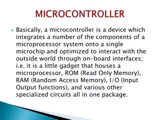
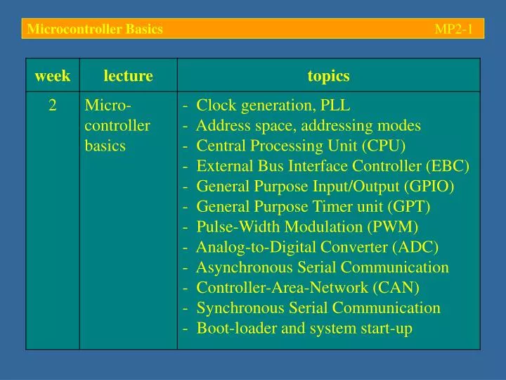
Microcontroller Basics MP2- 1. Microcontroller Basics MP2- 2. Typical microcontroller hardware units. Example: Phytec phyCORE-167. - Small single-board computer (SBC) with an Infineon C167CR microcontroller, 256 kB external RAM and 256 kB external (Flash) EEPROM.

E N D
Microcontroller Basics MP2-2 Typical microcontroller hardware units Example: Phytec phyCORE-167 - Small single-board computer (SBC) with an Infineon C167CR microcontroller, 256 kB external RAM and 256 kB external (Flash) EEPROM
Microcontroller Basics MP2-3 Typical microcontroller hardware units
Microcontroller Basics MP2-4 Typical microcontroller hardware units - Phase-Locked Loop (PLL) clock generation:User configurable system bus clock frequency peripheral clock separate from CPU clock (switch off CPU clock in Idle Mode) • Direct drive (fCPU = fOSC) • Prescaler (2:1) • PLL operation(fCPU = 1.5 … 5 x fOSC)
Microcontroller Basics MP2-5 Typical microcontroller hardware units - 16 MB linear address space (24-bit addresses address space from 0 to 216 = 16,777,216 = FF’FFFF) - 256 segments of 64 kB each; all segments are subdivided into 4 pages of 16 kB each - Von Neumann architecture code and data share the same address space, all physically separated memory areas are mapped into the same address space (internal and external RAM, external Flash ROM and other EEPROMs, internal OTP, special function registers (SFR), etc.)
Microcontroller Basics MP2-6 Typical microcontroller hardware units - Segment 0 is the system segment holding internal RAM (2 kB), special function register area (SFR, 2 x 512 bytes) and possibly some internal ROM (up to 32 kB)
Microcontroller Basics MP2-7 Typical microcontroller hardware units - The upper 4 kB of the system segment hold 2 kB of internal RAM (F600 – FDFF) and two banks of special function registers: SFR (FE00 – FFFF) and ESFR (F000 – F1FF) - The C167CR-LM does not implement any internal (on-chip) ROM
Microcontroller Basics MP2-8 Typical microcontroller hardware units - Upper half of SFR and ESFR (shaded area) is implemented as bit-addressable memory (individual bits can be set and/or cleared without interference to neighbouring bits) - Fast 16-bit access to the internal RAM using Data-Page Pointer DPP3
Microcontroller Basics MP2-9 Typical microcontroller hardware units - The system stack is held in internal RAM (IRAM); it is used for the automatic saving of the system state upon entry and exit of trap and interrupt routines - 2 kByte of internal high-speed XRAM for user variables and a user stack for parameter passing
Microcontroller Basics MP2-10 Typical microcontroller hardware units - Central Processing Unit (CPU) 4 Data-Page Pointers (DPP0 – DPP3) for fast segment internal memory access (16-bit addressing)
Microcontroller Basics MP2-11 Typical microcontroller hardware units - Segmented addressing: Data Page Pointers (DPP) - Bits 14 and 15 select the DPP (0 – 3), the remaining 14 bits form a linear address within this data page - Need to initialize DPP (usually done by startup code)
Microcontroller Basics MP2-12 Typical microcontroller hardware units - Central Processing Unit (CPU) Multiple General Purpose Register banks in internal RAM; fast context switching using a Context Pointer
Microcontroller Basics MP2-13 Typical microcontroller hardware units - Addressing via the Context Pointer (CP) - General Purpose Registers (GPR) are selected using a 4-bit address (0 – 15, part of the machine code ) - GPR address = CP + 4-bit offset (*2)
Microcontroller Basics MP2-14 Typical microcontroller hardware units - Addressing via the Context Pointer (CP) - Context switching: reload Context Pointer (CP) with new base address - Instruction SCXT stores CP on the stack and reloads it with the new base address in one machine cycle
Microcontroller Basics MP2-15 Typical microcontroller hardware units - External Bus Interface Controller (EBC) - Required when the internal hardware units of the controller are not enough, e.g. too little RAM or ROM, additional peripherals are required (e.g. D/A converters, an Ethernet controller, etc.) - Some of the pins are now used as external address bus and/or data bus; the characteristics of these busses can be selected upon reset, i. e. during the initialisation of the controller: width (8- or 16-bit), multiplexed address/data bus, wait states, etc.)
Microcontroller Basics MP2-16 Typical microcontroller hardware units - External Bus Interface Controller (EBC) - Performance of multiplexed and de-multiplexed bus: - Fastest access with de-multiplexed busses (no need for time-wasting latching); price to pay: more I/O lines are tied up by the address and/or data bus
Microcontroller Basics MP2-17 Typical microcontroller hardware units - External Bus Interface Controller (EBC) - Special Function Registers allow a number of memory windows to be defined; configuration parameters include: base address, window size, timing characteristics, wait states, etc. - Access to an address within any of these memory windows results in the generation of a corresponding chip select signal (/CS); these signals can be used to physically enable an external device (e.g. a Flash ROM chip, a UART chip, a CAN transceiver, etc.)
Microcontroller Basics MP2-18 Typical microcontroller hardware units - External Bus Interface Controller (EBC) - On the phyCORE-167:/CS0 selects FLASH bank (U1),/CS1 selects RAM bank (U2/U3), /CS2 selects optional UART (U7) - /CS3 and /CS4 can be used for additional peripheral units (e.g. memory mapped I/O units such as some D/A converters, CAN transceivers, etc.)
Microcontroller Basics MP2-19 Typical microcontroller hardware units - External Bus Interface Controller (EBC) - EBC is commonly configured during system start-up, i. e. in the startup code (software) or by tying some of the I/O lines to high/low during reset (hardware) - Dynamic switching of bus mode is possible - Example: System start-up in single chip mode – the external bus interface is deactivated – followed by a subsequent switch to software configured system constellation with external peripheral units (e.g. the user has plugged in a memory stick)
Microcontroller Basics MP2-20 Typical microcontroller hardware units - General Purpose Input/Output (GPIO) - The C167CR has 111 I/O lines, organised in 16-bit as well as 8-bit ports - All GPIO ports are bit-addressable (they are memory mapped in the bit-addressable region of the SFR) - True bi-directional ports, switched to high-impedance (hi-Z) when configured as inputs - Two different output drivers can be selected: push-pull and open-drain
Microcontroller Basics MP2-21 Typical microcontroller hardware units - General Purpose Input/Output (GPIO) - Input thresholds are normal TTL logic thresholds (ViH = 2.0 V, ViL = 0.8 V) - For noisy input signals inputs can be re-configured to CMOS logic thresholds (ViH = 3.7 V, ViL = 1.3 V); improved hysteresis between High and Low
Microcontroller Basics MP2-22 Typical microcontroller hardware units - General Purpose Input/Output (GPIO) - Push-pull output drivers: both states (high/low) are actively driven to 5 V or 0 V, respectively - Open-drain output drivers: upper transistor always switched off; only the low state (0 V) is enforced; an external pull-up resistor is required
Microcontroller Basics MP2-23 Typical microcontroller hardware units - General Purpose Input/Output (GPIO) - Edge characteristics of the output drivers (transition times during switching from high to low and vice versa) can be selected as slow or fast
Microcontroller Basics MP2-24 Typical microcontroller hardware units - General Purpose Timer unit (GPT) - Multi-functional unit for the production and analysis of time-varying signals - May be used for timing, event counting, pulse width measurement, pulse generation (PWM), frequency multiplication, etc. - Essentially a 16-bit register that is incremented or decremented at selected events (internal clock, external signals, etc.); interrupts can be triggered upon reaching pre-programmed threshold values
Microcontroller Basics MP2-25 Typical microcontroller hardware units - General Purpose Timer unit (GPT) - Example: Timer T3 - Pre-scaler reduces the effective clock frequency; TxOUT can be driven high when T3 elapses
Microcontroller Basics MP2-26 Typical microcontroller hardware units - General Purpose Timer unit (GPT) - Pre-scaling: ftimer = fCPU/23+n (n = 0 … 7); without this, the maximum period of the timer would be:216 / fCPU = 65,536 / (20106) = 3.27 10-3 s = 3.3 ms; this is often not long enough for slowly varying signals and processes (e.g. mechatronics systems) - Maximum pre-scale value (n = 7) reduces the effective timer clock to 20106/210 19.53 kHz; maximum period now: 216 / (19.53103) 3.36 s
Microcontroller Basics MP2-27 Typical microcontroller hardware units - General Purpose Timer unit (GPT) - For even slower signals: Cascade a pair of 16-bit timers to form a 32-bit timer; maximum period:232 / (19.53103) 220103 s 61.08 h
Microcontroller Basics MP2-28 Typical microcontroller hardware units - General Purpose Timer unit (GPT) - Example: GPT used in counter mode - Can count rising edges, falling edges or both
Microcontroller Basics MP2-29 Typical microcontroller hardware units - Asynchronous Serial Communication (ASC) - Provides serial communication between the C and other Cs and/or external peripherals - Full-duplex asynchronous communication up to 1.03 MBaud (1.03106 bps, at 33 MHz CPU clock) - Personal Computers (PC) often do not support rates above 230.4 kBaud - Double-buffered Tx and Rx data registers allow for back-to-back data transfer (without gaps)
Microcontroller Basics MP2-30 Typical microcontroller hardware units - Asynchronous Serial Communication (ASC) - Pins RxD0 and TxD0 are interfaced to an external UART transceiver chip; signal conversion TTL RS-232:> +3 V high, < - 3 V low, output levels: ±12 V
Microcontroller Basics MP2-31 Typical microcontroller hardware units - Controller-Area-Network (CAN, V2.0b) - Developed by BOSCH (1986); originally aimed at X-by-wire applications in the car manufacturing industry (CAr Network bus) - Today one of the most important communication standards for embedded systems - Deterministic protocol for serial communication via a 2/3-wire linear bus topology - Maximum data rate: 1 MBit/s
Microcontroller Basics MP2-32 Typical microcontroller hardware units - High-Speed Synchronous Serial Communication - Full-duplex serial communication with maximum transmission rate of 8.25 MBaud - Serial clock signal can be generated by the SSC unit (master mode) or detected (slaved mode) - Mainly used for high-speed communication with external peripherals (e.g. EEPROMS, D/A converters, other controllers, etc.) - Communication to multiple receivers possible via wired-AND circuit
Microcontroller Basics MP2-33 Typical microcontroller hardware units - Watchdog timer (dead-man button) - Allows recovery from software and/or hardware failures that make the controller ‘hang’ - A hardware reset is triggered periodically; programmers have to ensure that the watchdog timer register is cleared before this happens
Microcontroller Basics MP2-34 Typical microcontroller hardware units - Pulse Width Modulation unit (PWM) - Allows generation of PWM signals - Period register and Pulse Width register define the shape of the generated pulse sequence - Frequency based on CPU clock (fCPU)
Microcontroller Basics MP2-35 Typical microcontroller hardware units - Unipolar Analog-Digital Converter (ADC) - 16 A/D conversion channels (multiplexed) - ADC unit with 10-bit resolution and integrated sample-and-hold amplifier (SHA) - External analogue reference voltage (VAREF, VAGND) - Minimum conversion time: 7.76 s - Channel scanning mode allows efficient acquisition of multiple signal sources
Microcontroller Basics MP2-36 Typical microcontroller hardware units - Unipolar Analog-Digital Converter (ADC) - VAREF allowed range: 4.0 V … VDD + 0.1 V VAGND allowed range: VSS – 0.1 V … VSS + 0.2 V
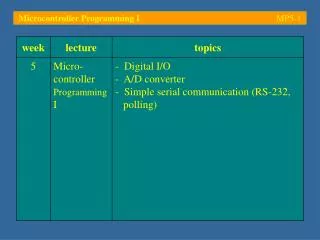
Microcontroller Basics MP2-37 System start-up (boot process) - Embedded systems most frequently boot … … from on-board memory mapped Flash ROM devices (several kB – 1 GB) … from bootable solid-state Flash disks (up to 100 GB, ATA-6, 100 MB/s transfer rate) … using a bootstrap loader via the serial interface (RS-232, CAN) … or through some other network connection (TCP/IP on Ethernet, Dynamic Host Control Protocol – DHCP, etc.)
Microcontroller Basics MP2-38 System start-up: Booting from (Flash) EEPROM - The system is (hardware) configured to map the EEPROM into the section of the address space which contains the RESET vector - Upon RESET, the code this vector points to is executed; this is the start-up code which takes care of the system initialization as (software) configured - The initialization code might re-configure the memory layout to what is required at run-time (e.g. after having checked what hardware modules have been plugged in, etc.)
Microcontroller Basics MP2-39 System start-up: Bootstrap loader using RS-232 - Mechanism for the transfer of a short program through the serial interface into the internal RAM of the controller - The bootstrap loader is activated by pulling low pin P0L.4 (port 0, pin 4) at the end of reset - The controller then scans serial reception line RxD0 for a zero-byte; the duration of this signal is used to detect the baud rate - An acknowledgement is sent and a short (32-byte) program is downloaded and executed
Microcontroller Basics MP2-40 System start-up: Bootstrap loader using RS-232 - The 32-byte user program is often used for the subsequent download of the actual program (which usually is much larger than 32 bytes!) subsequent download of actual user program
Microcontroller Basics MP2-41 System start-up: Bootstrap loader using RS-232 - During bootstrap mode, the User ROM at 0x0000 is replaced by the Boot ROM P0L.4 = low at the end of reset (bootstrap mode) P0L.4 = high at the end of reset (bootstrap mode) - A software reset marks the end of bootstrap mode; code execution will then be redirected to 0x0000