Download
1 / 48
770 likes | 3k Views
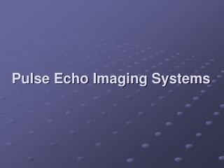
Chapter3 Pulse-Echo Ultrasound Instrumentation. 윤성수. contents. ▣ Pulse-Echo Ultrasound □ Pulsing Characteristics and Duty Factor ▣ Instrumentation □ Beam former □ Pulse Transmitter □ Receiver ▣ Ultrasound scanning ▣ Scanners □ Linear array transducers

E N D
contents ▣ Pulse-Echo Ultrasound □ Pulsing Characteristics and Duty Factor ▣ Instrumentation □ Beam former □ Pulse Transmitter □ Receiver ▣ Ultrasound scanning ▣ Scanners □ Linear array transducers □ Curvilinear array transducers □ Phased array transducers ▣ Frame rate and scanning speed limitations
Pulse-Echo Ultrasound □ The Range Equation □ T : Pulse Echo travel time □ c : speed of ultrasound in target material
Pulse-Echo Ultrasound □ Pulse Duration Pulse Duration↓ ⇒ Axial resolution↑ □ Pulse repetition period : Wait for Echo pulse PP↑ ⇒ frame rate ↓ □ Duty Factor
Beam former □ 구현방식 ▶ Analog vs Digital □ Beam steering and focusing (pulse delay sequence) ▶ transmit focusing ▶ dynamic focusing of received echo ▶ controls the beam direction
Beam former □ 구현방식 ▶ Analog ①반사신호를 한 곳에 모으는 시간이 20~40ns로 편차가 커 선명한 의료영상 구현 어려움 ② 인체 한 부위의 초점 위치를 제외한 나머지 부위에 대해선 수신 focusing을 구현할 수 없음
Beam former □ 구현방식 ▶ Digital Stable : external factor (ex. temperature) ② programmability ③ wide range of signal frequency
Beam former □ Beam steering and focusing (pulse delay sequence) ▶ transmit focusing ▶ dynamic focusing of received echo ▶ controls the beam direction array transmitter different time delay focusing Transmit focusing
Beam former □ Beam steering and focusing (pulse delay sequence) ▶ transmit focusing ▶ dynamic focusing of received echo ▶ controls the beam direction same delayed signal array transducer different time delay focused signal reflector Dynamic focusing of received echo
Beam former □ Beam steering and focusing (pulse delay sequence) ▶ transmit focusing ▶ dynamic focusing of received echo ▶ controls the beam direction Controls the beam direction
Pulse transmitter □ Pulse transmitter ▶ provide electrical signals for exciting transducer ① Transmit power ↑ ② Higher intensity sound wave ③ Higher amplitude echo signal ④ Appear brighter and weaker reflectors In the display But acoustical exposure to the patient↑
Pulse transmitter □ Pulse transmitter ▶ provide electrical signals for exciting transducer High output power (MI is 0.8) Low output power (MI is 0.2)
receiver □ Procedure of the receiver
amplify(Receiver) • □ Preamplifier • Boosts echo signals • protect the receiver from high-voltage • □ problem : amplify noise
compensate(Receiver) □ Gain adjustments ▶ Overall gain control : Increase amplification at all depths Low gain High gain
compensate(Receiver) □ Gain adjustments ▶ Overall gain control : Increase amplification at all depths Low gain High gain
compensate(Receiver) □ Gain adjustments ▶ Swept gain or TGC(time gain compensation) : Attenuation compensation depending depth
compensate(Receiver) □ Gain adjustments ▶ Swept gain or TGC ▶ Slider bar TGC control
compensate(Receiver) □ Gain adjustments ▶ 3-Knob TGC control
compensate(Receiver) □ Gain adjustments ▶ Internal time-varied gain : automatically set swept gain ▶ Lateral gain
compensate(Receiver) □ Dynamic frequency tuning ▶ Higher frequency sound waves are attenuated more rapidly and penetrate less deeply than lower frequencies.
compensate(Receiver) □ Dynamic frequency tuning ▶ Higher frequency sound waves are attenuated more rapidly and penetrate less deeply than lower frequencies. ▶ shallow regions higher frequencies deeper regions lower frequencies
Dynamic range and compression(Receiver) □ Dynamic range ▶ Limited input signal amplitude range to respond effectively ▶ Threshold < Input signal < Saturation
Dynamic range and compression(Receiver) □ Log compression ▶ Receiver : 100~120dB Memory : 40~45dB Monitor(contrast) : 20~30dB Log Compression
Dynamic range and compression(Receiver) □ Log compression ▶ Low dynamic range : High contrast High dynamic range : Low contrast
demodulation(Receiver) □ Demodulation ▶ Convert the amplified echo signal into a single pulse Input signal → rectification → smoothing
Reject(Receiver) □ Reject ▶ reject eliminates both low level electronic noise and low level echoes
Reject(Receiver) □ Reject ▶ Adaptive threshold processing
Ultrasound scanning □ A – mode(amplitude mode) ▶ shows echo amplitude versus reflector distance ▶ only presents echo data from a single beam line(limited uses)
Ultrasound scanning □ A – mode(amplitude mode) ▶ shows echo amplitude versus reflector distance ▶ only presents echo data from a single beam line(limited uses) ▶ ophthalmological applications
Ultrasound scanning □ B – mode(brightness mode) ▶ echo signals are converted to intensity-modulated dots ▶ brightness ∝ echo signal amplitude
Ultrasound scanning A - mode B - mode
Ultrasound scanning □ M – mode(motion mode) ▶ by slowly sweeping a B-mode trace across a screen ▶ depth on one axis and time on an orthogonal axis
Ultrasound scanning □ M – mode(motion mode) ▶ velocity of a reflector is estimated from ∆d ∆t
Ultrasound b-mode scanning □ Image build-up ▶ called 2-D image ▶ echoes are positioned along a line that corresponds to the beam axis
scanners □ Linear array transducers ▶ small rectangular elements lined up side by side ▶ parallel beam line
scanners □ Linear array transducers ▶ small rectangular elements lined up side by side
scanners □ Convex array transducers ▶ same principles as a linear array ▶ beam lines are not parallel, emerge at different angles
scanners □ Convex array transducers ▶ larger imaged field than linear array
scanners □ Phased array transducers ▶ electronically steered at various angles ▶ electronic focusing
scanners □ Phased array transducers ▶ through the intercostal (small entrance window) ▶ cardiac imaging
scanners □ Mechanical scan ▶ two to four separate transducers positioned in different locations on the rim of rotating wheel
Frame rate and scanning speed limitations □ Maximum frame rate ▶ D : depth C : speed of sound in tissue (1540 m/s) N : the number of lines
Frame rate and scanning speed limitations □ Maximum frame rate ▶ D : depth C : speed of sound in tissue (1540 m/s) N : the number of lines D ↑⇒ Frame Rate↓ N↑⇒ Frame Rate↓ N↑⇒ Frame Rate↓ Smaller image size Resolution 유지