Download
1 / 16
160 likes | 272 Views
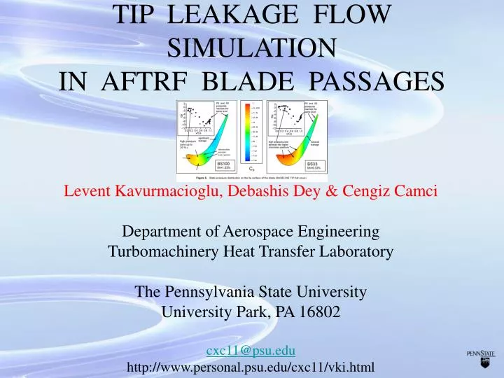
TIP LEAKAGE FLOW SIMULATION IN AFTRF BLADE PASSAGES. Levent Kavurmacioglu, Debashis Dey & Cengiz Camci Department of Aerospace Engineering Turbomachinery Heat Transfer Laboratory The Pennsylvania State University University Park, PA 16802 cxc11@psu.edu

E N D
TIP LEAKAGE FLOW SIMULATIONIN AFTRF BLADE PASSAGES Levent Kavurmacioglu, Debashis Dey & Cengiz Camci Department of Aerospace Engineering Turbomachinery Heat Transfer Laboratory The Pennsylvania State University University Park, PA 16802 cxc11@psu.edu http://www.personal.psu.edu/cxc11/vki.html
Figure 1, 3D computational grid for the AFTRF turbine rotor flow simulations
130x65x88 105x51x74 75x65x26 50x51x26 Figure 2, Grid structure near the baseline tip configuration
Figure 3 Tip leakage visualization planes (cross-stream direction & blade height)
Figure 6, Velocity vectors at various planes in the tip gap (BASELINE TIP - full cover)
Figure 7 , Leakage Flow Patterns in the tip gap space inside cross stream planes (BASELINE TIP, full cover)
Figure 7 , Leakage Flow Patterns in the tip gap space inside cross stream planes (BASELINE TIP, full cover)
Figure 8, Leakage flow patterns in planes parallel to the tip surface, (BASELINE TIP, full cover)
Figure 8, Leakage flow patterns in planes parallel to the tip surface, (BASELINE TIP, full cover)
Figure 8, Leakage flow patterns in planes parallel to the tip surface, (BASELINE TIP, full cover)
TIP LEAKAGE FLOW SIMULATIONIN AFTRF BLADE PASSAGES Levent Kavurmacioglu, Debashis Dey & Cengiz Camci Department of Aerospace Engineering Turbomachinery Heat Transfer Laboratory The Pennsylvania State University University Park, PA 16802 cxc11@psu.edu http://www.personal.psu.edu/cxc11/vki.html