Download
1 / 37
370 likes | 374 Views
Chapter 12 Objectives. Advanced Topic: Computer Network Architecture. Become familiar with the fundamentals of computer network architectures. Learn the basic components of a local area network. Become familiar with the general architecture of the Internet. 12.1 Introduction.

E N D
Chapter 12 Objectives Advanced Topic: Computer Network Architecture • Become familiar with the fundamentals of computer network architectures. • Learn the basic components of a local area network. • Become familiar with the general architecture of the Internet. Lecture
12.1 Introduction • The network is a crucial component of today’s computing systems. • Resource sharing across networks has taken the form of multitier architectures having numerous servers, sometimes far removed from the users of the system. • If you think of a computing system as collection of workstations and servers, then surely the network is the system bus of this configuration. Lecture
12.2 Early Business Computer Networks • The first computer networks consisted of a mainframe host that was connected to one or more front end processors. • Front end processors received input over dedicated lines from remote communications controllers connected to several dumb terminals. • The protocols employed by this configuration were proprietary to each vendor’s system. • One of these, IBM’s SNA became the model for an international communications standard, the ISO/OSI Reference Model. Lecture
12.3 Early Academic and Scientific Networks • In the 1960s, the Advanced Research Projects Agency funded research under the auspices of the U.S. Department of Defense. • Computers at that time were few and costly. In 1968, the Defense Department funded an interconnecting network to make the most of these precious resources. • The network, DARPANet, designed by Bolt, Beranek, and Newman, had sufficient redundancy to withstand the loss of a good portion of the network. • DARPANet, later turned over to the public domain, eventually evolved to become today’s Internet. Lecture
12.4 Network Protocols I ISO/OSI Reference Model • To address the growing tangle of incompatible proprietary network protocols, in 1984 the ISO formed a committee to devise a unified protocol standard. • The result of this effort is the ISO Open Systems Interconnect Reference Model (ISO/OSI RM). • The ISO’s work is called a reference model because virtually no commercial system uses all of the features precisely as specified in the model. • The ISO/OSI model does, however, lend itself to understanding the concept of a unified communications architecture. Lecture
12.4 Network Protocols I ISO/OSI Reference Model • The OSI RM contains seven protocol layers, starting with physical media interconnections at Layer 1, through applications at Layer 7. Lecture
Why Study OSI? • Still an excellent model for conceptualizing and understanding protocol architectures • More granularity in functionality - more functional delineation • Key points: • Modular • Hierarchical (chain of command, pecking order) • Boundaries between layers (called interfaces) NOTE: the protocols or functionality with in the layer could change however, the interface remains the same – this facilitates the flexibility Lecture
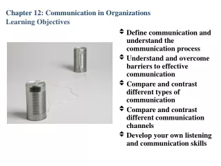
Advantages of Layering • Easier application development • Network can change without all programs being modified • Breaks complex tasks into subtasks • Each layer handles a specific subset of tasks • Communication occurs • between different layers on the same node or stack (INTERFACES) • between similar layers on different nodes or stacks (PEER-TO-PEER PROCESSES Lecture
Top Layer Top Layer Some Intermediate Layer Some Intermediate Layer Bottom Layer Bottom Layer OSI’s Layered Approach Example Network A Network B Actual commands invoked, presentation Facilitate the actual communications Network interfaces, raw bits How does peer-to-peer communication work ? Lecture
OSI Physical Layer • Responsible for transmission of bits • Always implemented through hardware • Encompasses mechanical, electrical, and functional interfaces • Encoding issues: how 0’s and 1’s are converted to signals • Transport medium: Coaxial, Twisted Pair, Optical, etc.. • Transmission Rate/Data Rate – how fast to send bits • Transmission mode: transmission direction (simplex, duplex) • Physical Topology: network layout Lecture 2
Actually sends the packets (groups of frames) from node to node using a routing algorithm Network Layer Data Link Layer Takes raw data (bits) and transform them into frames, error control, etc. Transmit and receive the raw data (bits) Physical Layer OSI Data Link Layer • Responsible for error-free, reliable transmission of data • Framing, Flow control, Error control (detection/correction) • Makes use of physical address because with in the same network Lecture 2
OSI Network Layer • Responsible for routing of messages through networks • Concerned with type of switching used (circuit v. packet) • Handles routing among different networks • NOTE: with in the same network, only the DATA LINK layer is needed – amongst multiple networks, the NETWORK LAYER is needed • No need for routing with in the same network (LAN) • Routing across “internetworks” • Makes use of logical address vs physical address because not with in same network Lecture 2
Concerned with an error-free end-to-end flow of data Transport Network Layer Actually sends the packets (groups of frames) from node to node using a routing algorithm Data Link Layer Takes raw data (bits) and transform them into frames OSI Network Layer Lecture 2
OSI Network Layer Lecture 2
OSI Transport Layer • Isolates messages from lower and upper layers • Breaks down message size (segmentation) (down) and performs re-assembly (up) • Monitors quality of communications channel (oversee all hops) • Selects most efficient communication service necessary for a given transmission (could change over hops) • Flow and Error control for Source and Sink Lecture 2
OSI Session Layer • Establishes logical connections between systems (up/down) • Manages log-ons, password exchange, log-offs (up/down) • Terminates connection at end of session (up/down) Lecture 2
OSI Session Layer Lecture 2
OSI Presentation Layer • Provides format and code conversion services • Examples • File conversion from ASCII to EBDIC • Invoking character sequences to generate bold, italics, etc on a printer • The source and sink could operate using different encoding schemes – the presentation layer makes the translations • Security • Compression Lecture 2
OSI Application Layer • Provides access to network for end-user (end-user being a human being or software application) • User’s capabilities are determined by what items are available on this layer (ie. remote log-in, file transfer, email service, directory service, etc.) Lecture 2
What happens at the End and Intermediate Nodes ? Rx Tx 7 Intermediate Nodes 3 1 1 B C Q T A Z Lecture 2
Recap - OSI’s Layered Approach • between different layers on the same node or stack (INTERFACE) • between similar layers on different nodes or stacks (PEER-TO-PEER PROCESSES) Lecture 2
An exchange using the OSI model Explain encapsulation and decapsulation Lecture 2
COMPLEXITY TO CONSIDER • Any particular node in an internetwork can be functioning as follows simultaneously: • Tx to other internetwork nodes • Rx from other internetwork nodes • Intermediate node to some other internetwork nodes Lecture 2
The File Transfer Program issues a command to the Application Layer Application passes it to Presentation, which may reformat, encrypt, encode, compress, passes to Session (adds overhead) Session requests a connection, passes to Transport (adds overhead) Transport breaks file into chunks, adds error-checking and flow-control info, process-to-process, passes to Network (adds overhead) Network selects the data’s route (internetworking), passes to Data Link (adds overhead) Data Link adds error-control and flow-control info, passes to Physical (adds overhead) Physical translates bits to signal and transmits the signal, which includes information added by each layer OSI in Action: Outgoing File Transfer Lecture 2
Physical receives signal and translates to bits, passes to Data Link Data Link checks for errors and performs flow control on bits, formulates bits into some formation (frames), passes to Network Network verifies routing (if intermediate node, determines next hop), passes to Transport Transport checks for errors and performs flow control on the chunks, reassembles the chunks, passes to Session Session determines if transfer is complete, may end session, passes to Presentation Presentation may reformat, perform conversions, decode, decrypt, decompress, pass to Application layer Application presents results to user (e.g. updates FTP program display) OSI in Action: Incoming File Transfer Lecture 2
12.5 Network Protocols II TCP/IP Network Architecture • It has a lean 3-layer protocol stack that can be mapped to five of the seven in the OSI model. • TCP/IP can be used with any type of network, even different types of networks within a single session. • TCP/IP is the de facto global data communications standard.
12.5 Network Protocols II TCP/IP Network Architecture • The IP Layer of the TCP/IP protocol stack provides essentially the same services as the Network and Data Link layers of the OSI Reference Model. • It divides TCP packets into protocol data units called datagrams, and then attaches routing information.
12.5 Network Protocols II TCP/IP Network Architecture • Datagrams can take any route available to them without human intervention. • The concept of the datagram was fundamental to the robustness of ARPAnet, and now, the Internet.
12.5 Network Protocols II TCP/IP Network Architecture • The current version of IP, IPv4, was never designed to serve millions of network components scattered across the globe. • It limitations include 32-bit addresses, a packet length limited to 65,635 bytes, and that all security measures are optional. • Furthermore, network addresses have been assigned with little planning which has resulted in slow and cumbersome routing hardware and software. • We will see later how these problems have been addressed by IPv6.
IP datagram • IP datagram is variable length consisting of two parts (header, data) • Header is 20-60 bytes & contains routing and deliver info • Ver – version of IP • HLEN – header length – total length of the header field (in 4-byte words or units) • Service type – now called Differentiated Services – tells the service type (ie. ftp, dns, telnet, etc..) – will come back to this • Total length – defines the total length of the datagram including the header – need this to determine if padding is needed – recall Ethernet frame can range 46-1500 bytes – so if the IP datagram is less than 46 bytes (need padding) • Identification – used for fragmentation – networks that are not able to encapsulate the full IP datagram will need to fragment – will come back to this • Flags – used for fragmentation – will come back to this • Fragmentation offset – used for fragmentation – will come back to • Time to live – datagram life time as it travels – used to control the number of hops (routers) a datagram can traverse – fix infinite loop problems • Protocol – defines the higher level protocol (ie. TCP, UDP, ICMP, ICMP, etc..) that’s using the service of the IP layer – since the IP Muxes data from the Transport layer – this field is used to demux Lecture
12.5 Network Protocols II TCP/IP Network Architecture • IPv4 Address Space
12.5 Network Protocols II TCP/IP Network Architecture • Transmission Control Protocol (TCP) is the consumer of IP services. • It engages in a conversation-- a connection-- with the TCP process running on the remote system. • A TCP connection is analogous to a telephone conversation, with its own protocol "etiquette."
TCP segment format 20-60 bytes • Cover URG, ACK, PSH, RST, SYN and FIN next • Urgent Pointer – used when the segment contains urgent data • Cover Options next Lecture
Control field • These bits or flags enable flow control, connection establishment and termination, connection abortion and the mode of data transfer Lecture
Options • End of Option - used as padding at the end • No operation – used as padding in between options • Maximum segment size- defined the largest possible data size • Window Scale Factor – allows scaling of the sliding window • Time Stamp – Tx fills this field when the segment is sent Lecture
12.5 Network Protocols II TCP/IP Network Architecture • As part of initiating a connection, TCP also opens a service access point (SAP) in the application running above it. • In TCP, this SAP is a numerical value called a port. • The combination of the port number, the host ID, and the protocol designation becomes a socket, which is logically equivalent to a file name (or handle) to the application running above TCP. • Port numbers 0 through 1023 are called “well-known” port numbers because they are reserved for particular TCP applications.
Connection establishment using three-way handshake (A) Server starts by telling TCP it can accept a connection – done by doing a “passive open” (2nd) Server sends a SYN + ACK segment (2 bits set) – the ACK acknowledges the client’s SYN segment – and the SYN synchs the server with the client in the opposite direction (implementing full duplex) – the server also sends the desired window size to the client (B) When client is ready to connect – it issues an “active open” to a specific server (1st) Client sends the first segment – the SYN bit (synchronization) is set and it has a randomly generated starting sequence number – carries no data (3rd) Client sends a third segment, with the ACK bit set, to acknowledge the server’s segment – in some cases, the segment can also send the FIRST chunk of data to the server Lecture