Download
1 / 45
600 likes | 800 Views
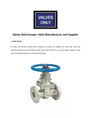
Boiler Safety Valve. Safety Valves - Definitions. In most national standards, specific definitions are given for the terms associated with safety and safety relief valves. There are several differences between the terminology used in the USA and Europe.

E N D
Boiler Safety Valve Kalyan Chatterjea/June 2005
Safety Valves - Definitions • In most national standards, specific definitions are given for the terms associated with safety and safety relief valves. • There are several differences between the terminology used in the USA and Europe. • One of the most important differences is that a valve referred to as a 'safety valve' in Europe is referred to as a 'safety relief valve' or 'pressure relief valve'in the USA. • In addition, the term 'safety valve' in the USA generally refers specifically to the full-lift type of safety valve used in Europe. Kalyan Chatterjea/June 2005
Safety Valves - Definitions • The ASME / ANSI PTC25.3 standards applicable to the USA define the following generic terms: • Pressure relief valve - A spring-loaded pressure relief valve which is designed to open to relieve excess pressure and to re-close and prevent the further flow of fluid after normal conditions have been restored. • It is characterized by a rapid-opening ‘pop’ action or by opening in a manner generally proportional to the increase in pressure over the opening pressure. • It may be used for either compressible or incompressible fluids, depending on design, adjustment, or application. Kalyan Chatterjea/June 2005
Safety Valves - Definitions • The ASME / ANSI PTC25.3 standards applicable to the USA define the following generic terms: • Safety valve - A pressure relief valve actuated by inlet static pressure and characterised by rapid opening or pop action.Safety valves are primarily used with compressible gases and in particular for steam and air services. However, they can also be used for process type applications where they may be needed to protect the plant or to prevent spoilage of the product being processed. Kalyan Chatterjea/June 2005
Safety Valves - Definitions • The ASME / ANSI PTC25.3 standards applicable to the USA define the following generic terms: • Relief valve - A pressure relief device actuated by inlet static pressure having a gradual lift generally proportional to the increase in pressure over opening pressure. Relief valves are commonly used in liquid systems, especially for lower capacities and thermal expansion duty. They can also be used on pumped systems as pressure overspill devices. . Kalyan Chatterjea/June 2005
Safety Valves - Definitions • The ASME / ANSI PTC25.3 standards applicable to the USA define the following generic terms: • Safety relief valve - A pressure relief valve characterised by rapid opening or pop action, or by opening in proportion to the increase in pressure over the opening pressure, depending on the application, and which may be used either for liquid or compressible fluid.In general, the safety relief valve will perform as a safety valve when used in a compressible gas system, but it will open in proportion to the overpressure when used in liquid systems, as would a relief valve. Kalyan Chatterjea/June 2005
Safety Valves - Definitions • The European standards (BS 6759 and DIN 3320) provide the following definition: • Safety valve - A valve which automatically, without the assistance of any energy other than that of the fluid concerned, discharges a certified amount of the fluid so as to prevent a predetermined safe pressure being exceeded, and which is designed to re-close and prevent the further flow of fluid after normal pressure conditions of service have been restored. Kalyan Chatterjea/June 2005
Typical Safety Valves Kalyan Chatterjea/June 2005
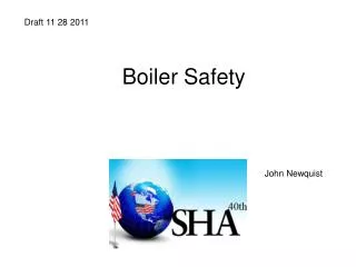
ASME Safety Valve • The basic elements of the design consist of a right angle pattern valve body with the valve inlet connection, or nozzle, mounted on the pressure-containing system. • The outlet connection may be screwed or flanged for connection to a piped discharge system. Kalyan Chatterjea/June 2005
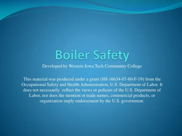
DIN Safety Valve • The basic elements of the design consist of a right angle pattern valve body with the valve inlet connection, or nozzle, mounted on the pressure-containing system. • The outlet connection may be screwed or flanged for connection to a piped discharge system. Kalyan Chatterjea/June 2005
Safety Valve Design • The valve inlet (or approach channel) design can be either a full-nozzle or a semi-nozzle type. • A full-nozzle design has the entire ‘wetted’ inlet tract formed from one piece. • The approach channel is the only part of the safety valve that is exposed to the process fluid during normal operation, other than the disc, unless the valve is discharging. • Full-nozzles are usually incorporated in safety valves designed for process and high pressure applications, especially when the fluid is corrosive. Kalyan Chatterjea/June 2005
Safety Valve Design • the semi-nozzle design consists of a seating ring fitted into the body, the top of which forms the seat of the valve. • The advantage of this arrangement is that the seat can easily be replaced, without replacing the whole inlet. Kalyan Chatterjea/June 2005
Safety Valve Design • The disc is held against the nozzle seat (under normal operating conditions) by the spring, which is housed in an open or closed spring housing arrangement (or bonnet) mounted on top of the body. • The discs used in rapid opening (pop type) safety valves are surrounded by a shroud, disc holder or huddling chamber which helps to produce the rapid opening characteristic. Kalyan Chatterjea/June 2005
Safety Valve Design • The closing force on the disc is provided by a spring, typically made from carbon steel. The amount of compression on the spring is usually adjustable, using the spring adjuster, to alter the pressure at which the disc is lifted off its seat. Kalyan Chatterjea/June 2005
Safety ValveDesign • Standards that govern the design and use of safety valves generally only define the three dimensions that relate to the discharge capacity of the safety valve, namely the flow (or bore) area, the curtain area and the discharge (or orifice) area. Kalyan Chatterjea/June 2005
Safety ValveDesign • Flow area - The minimum cross-sectional area between the inlet and the seat, at its narrowest point. The diameter of the flow area is represented by dimension ‘d’ in Figure Kalyan Chatterjea/June 2005
Safety ValveDesign • Curtain area - The area of the cylindrical or conical discharge opening between the seating surfaces created by the lift of the disk above the seat. The diameter of the curtain area is represented by dimension ‘d1’ in Figure. Kalyan Chatterjea/June 2005
Safety ValveDesign • Discharge area - This is the lesser of the curtain and flow areas, which determines the flow through the valve. Kalyan Chatterjea/June 2005
Safety ValveDesign • Valves in which the flow area and not the curtain area determines the capacity are known as full lift valves. These valves will have a greater capacity than low lift or high lift valves. Kalyan Chatterjea/June 2005
Safety Valve Design • Although the principal elements of a conventional safety valve are similar, the design details can vary considerably. • The DIN style valves (commonly used throughout Europe) tend to use a simpler construction with a fixed skirt (or hood) arrangement whereas the ASME style valves have a more complex design that includes one or two adjustable blowdown rings. • The position of these rings can be used to fine-tune the overpressure and blowdown values of the valve. Kalyan Chatterjea/June 2005
Safety Valve Design • For a given orifice area, there may be a number of different inlet and outlet connection sizes, as well as body dimensions such as centreline to face dimensions. • Furthermore, many competing products, particularly of European origin have differing dimensions and capacities for the same nominal size. Kalyan Chatterjea/June 2005
Safety Valve Design • For a given orifice area, there may be a number of different inlet and outlet connection sizes, as well as body dimensions such as centreline to face dimensions. • Furthermore, many competing products, particularly of European origin have differing dimensions and capacities for the same nominal size. Kalyan Chatterjea/June 2005
Safety Valve Operation - Lifting • When the inlet static pressure rises above the set pressure of the safety valve, the disc will begin to lift off its seat. • However, as soon as the spring starts to compress, the spring force will increase. • This means that the pressure would have to continue to rise before any further lift can occur, and for there to be any significant flow through the valve. Kalyan Chatterjea/June 2005
Safety Valve Operation - Lifting • The additional pressure rise required before the safety valve will discharge at its rated capacity is called the overpressure. • The allowable overpressure depends on the standards being followed and the particular application. • For compressible fluids, this is normally between 3% and 10%, and for liquids between 10% and 25%. Kalyan Chatterjea/June 2005
Safety Valve Operation - Lifting • In order to achieve full opening from this small overpressure, the disc arrangement has to be specially designed to provide rapid opening. • This is usually done by placing a shroud, skirt or hood around the disc. • The volume contained within this shroud is known as the control or huddling chamber. Kalyan Chatterjea/June 2005
Safety Valve Operation - Lifting • As lift begins and fluid enters the chamber, a larger area of the shroud is exposed to the fluid pressure. Kalyan Chatterjea/June 2005
Safety Valve Operation - Lifting • Since the magnitude of the lifting force (F) is proportional to the product of the pressure (P) and the area exposed to the fluid (A); (F = P x A), the opening force is increased. Kalyan Chatterjea/June 2005
Safety Valve Operation - Lifting • This incremental increase in opening force overcompensates for the increase in spring force, causing rapid opening. At the same time, the shroud reverses the direction of the flow, which provides a reaction force, further enhancing the lift. Kalyan Chatterjea/June 2005
Safety Valve Operation - Lifting • These combined effects allow the valve to achieve its designed lift within a relatively small percentage overpressure. For compressible fluids, an additional contributory factor is the rapid expansion as the fluid volume increases from a higher to a lower pressure area. Kalyan Chatterjea/June 2005
Safety Valve Operation – Re-sitting • Once normal operating conditions have been restored, the valve is required to close again, but since the larger area of the disc is still exposed to the fluid, the valve will not close until the pressure has dropped below the original set pressure. Kalyan Chatterjea/June 2005
Safety Valve Operation - Re • This plays a major role in ensuring that the valve opens fully within the small overpressure limit. For liquids, this effect is more proportional and subsequently, the overpressure is typically greater; 25% is common. Kalyan Chatterjea/June 2005
Safety Valve Operation – Re-sitting • The difference between the set pressure and this reseating pressure is known as the ‘blowdown’ • It is usually specified as a percentage of the set pressure. • For compressible fluids, the blowdown is usually less than 10% • For liquids, it can be up to 20%. Kalyan Chatterjea/June 2005
Relationship between Set Pressure, Overpressure & Blowdown Kalyan Chatterjea/June 2005
Relationship between Set Pressure, Overpressure & Blowdown • The design of the shroud must be such that it offers both rapid opening and relatively small blowdown • So that as soon as a potentially hazardous situation is reached, any overpressure is relieved, but excessive quantities of the fluid are prevented from being discharged. • At the same time, it is necessary to ensure that the system pressure is reduced sufficiently to prevent immediate reopening. Kalyan Chatterjea/June 2005
Set Pressure, Overpressure & Blowdown • The blowdown rings found on most ASME type safety valves are used to make fine adjustments to the overpressure and blowdown values of the valves Kalyan Chatterjea/June 2005
Set Pressure, Overpressure & Blowdown • The lower blowdown (nozzle) ring is a common feature on many valves. Kalyan Chatterjea/June 2005
Set Pressure, Overpressure & Blowdown • The upper blowdown ring is usually factory set and essentially takes out the manufacturing tolerances which affect the geometry of the huddling chamber. Kalyan Chatterjea/June 2005
Set Pressure, Overpressure & Blowdown • The lower blowdown ring is also factory set to achieve the appropriate code performance requirements but under certain circumstances can be altered. Kalyan Chatterjea/June 2005
Set Pressure, Overpressure & Blowdown • When the lower blowdown ring is adjusted to its top position the huddling chamber volume is such that the valve will pop rapidly, minimising the overpressure value but correspondingly requiring a greater blowdown before the valve re-seats. Kalyan Chatterjea/June 2005
Set Pressure, Overpressure & Blowdown • When the lower blowdown ring is adjusted to its lower position there is minimal restriction in the huddling chamber and a greater overpressure will be required before the valve is fully open but the blowdown value will be reduced. Kalyan Chatterjea/June 2005
Do you know your Boiler Safety Valve? • What is the primary function of a safety valve? • To maintain the pressure of a system within a specified range TRUE/FALSE • To protect life & property TRUE/FALSE • To extend working life of a pressure vessel TRUE/FALSE • To allow for gradual release of over pressure TRUE/FALSE Kalyan Chatterjea/June 2005
Do you know your Boiler Safety Valve? • What is the main operational differences between safety valves & relief valves? • Relief valve characteristic: Rapid opening or popping TRUE/FALSE • Safety valve characteristic: Gradual opening on increased pressure TRUE/FALSE Kalyan Chatterjea/June 2005
Do you know your Boiler Safety Valve? • Given d = 29 mm, d1 = 35 mm, L = 5 mm what would be the discharge area? • 550 mm2 • 617 mm2 • 661 mm2 • 693 mm2 Kalyan Chatterjea/June 2005
Do you know your Boiler Safety Valve? • Which of the following factor(s) combine to produce the rapid opening characteristics for most safety valves used in steam application ? • Rapid expansion of steam as the fluid volume increases TRUE/FALSE • Exposure of a greater disc surface area to steam TRUE/FALSE • To effect created by shroud TRUE/FALSE • All of the above TRUE/FALSE Kalyan Chatterjea/June 2005
Do you know your Boiler Safety Valve? • What is the function of the lower blowdown ring? • To adjust the blowdown value of the valve TRUE/FALSE • To adjust the set pressure of the valve TRUE/FALSE • To adjust the back pressure on the valve disc TRUE/FALSE • To adjust the overpressure & blowdown of the valve TRUE/FALSE Kalyan Chatterjea/June 2005