Download
1 / 6
60 likes | 175 Views
Light Precipitation Validation Experiment. LPVEx. FMI. Science Goals. Characterize the relative abilities of space-based W, Ku-, and Ka-band radars and microwave imagers and sounders to detect light. What are the detection limits of each instrument?

E N D
Science Goals • Characterize the relative abilities of space-based W, Ku-, and Ka-band radars and microwave imagers and sounders to detect light. • What are the detection limits of each instrument? • Can rainfall probabilities be assigned to Z and TB signatures? • Evaluate retrievals of rainfall intensity in shallow freezing level environments. • How does the ratio of cloud-rain impact PIA and PMW TBs? • How does the vertical structure of precipitation impact emission/attenuation-based algorithms? • What are the impacts of other algorithm assumptions including DSD and melting layer properties on rainrate estimates? • How do well are FOV-dependent factors such as beamfilling and multiple-scattering represented? • Determine the properties of the local environment that influence the characteristics of precipitation in this region. LPVEx 2010
Ground Instrumentation • Ground Sensors • Disdrometers: 2DVD (2) and Parsivel (6-10) • 10+ rain gauges • 5 SWE probes • ADMIRARI Radiometer (total LWP) • 3 C-band Doppler radars (fully adaptable scanning geometry) • Still looking for Ka- and or X-band radar • 2 Precipitation Occurrence Sensing Systems (POSS) • UHF Wind Profiler • 3 Micro Rain Radars (MRR) • SMEAR aerosol/flux tower • 6 Ceilometers • Sounding system and expendables at Jarvenpaa (+ twice daily soundings from St. Petersburg, Tallinn, and Jokioinen) LPVEx 2010
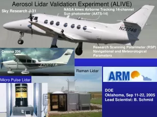
Aircraft & Research Vessel Z • Wyoming King Air • W-band cloud radar • Water content: DMT, Gerber, Nevzorov • Microphysics: 2D-P, CIP, CDP (FSSP/2D-C) • Aerosol: PCASP-100X, UWYO CCNC-100A • Ancillary: RH, T, altitude, wind speed • RV Aranda • Weather mast with disdrometers installed • Vaisala sounding system • Oceanographic measurements (conductivity, temperature, depth, Accoustic Doppler Current Profiler (ADCP), etc.) DSD/PSD RH and LWP T and z LPVEx 2010
Layout • Green = FMI Wx Stn • = Enhanced Obs. • = Vaisala WxTs (inc. rain) • Gray circles = 20 km radar range rings = Spiral = Stacked flight tracks Kerava NW Kerava NE Järvenpää Turku Maximum Extent of Flight Operations Kerava SW Kerava Emasalo Region of Likely Flight Operations Kumpula Ferry Kumpula SE Harmaja Kalbadaglund Gulf Stack Kumpula SW Ferry RV Aranda Ops. Spiral S1
Physical Validation Strategy Direct Evaluation • Coordinated airborne W-band radar with in situ ground-based, and ship-based μ-physics, precip., and thermodynamics. • In situ observations constrain DSD retrievals within C-band radar volumes. These 3D fields provide input to PMW and Ka/Ku-band simulators. • Cloud resolving model simulations with both GCE and RAMS provide another source of input to simulators. Measurement Observable Simulators Cloud Resolving Models & Satellite Simulators