Download
1 / 24
240 likes | 247 Views
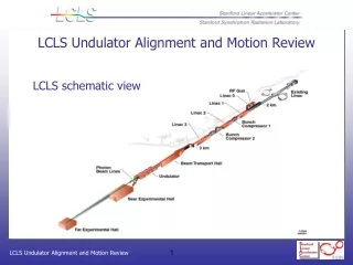
Undulator Alignment Diagnostic Systems. Introduction. Task & Tolerances ,. Description. Design Objectives & Instruments . Integration. Layout, Electronic & Local Control. Summary.

E N D
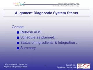
Undulator Alignment Diagnostic Systems • Introduction Task & Tolerances, • Description Design Objectives & Instruments • Integration Layout, Electronic & Local Control • Summary
Qstn.: # 2 “Is the expectedperformance of ADS high enough to cope with these class of tolerances...? ” Introduction… Why ADS? Statement: “ No accelerator around the globe has an Alignment Diagnostic System under routine operation ! ” Qstn.: # 1 “ Why do we propose LCLS should be the first...? ” Answr.:“ LCLS will operate in a new class of tolerances ! ”
Position control to reference lines over a distance of 140 Meter Y Y Reference Beam X X Reference U33 U1 Tracking Tolerances… Undulator Quadrupoles:σx = ~ 1 μm,σy = ~1 μm Introduction… The Task of ADS X-Ray Runs:Permanent transverse position tracking of 33 Undulator Segments on aSub-Micrometer scale. Undulator Segments : σx = ~10 μm, σy = ~ 5 μm
Description… ADSDesign Objectives • Resolution ~ 100 Nanometer in X & Y direction • Instrument Drift~ 100 Nanometer per day • Moving Range± 1.5 Millimeter in X & Y direction • Accuracy0.1 % of full Scale • AvailabilityPermanent, no interrupts
Description…Options of Technologies Horizontal & Vertical, needsvacuum, Limited by light sensor physics. • LASER • Stretched Wire Excellent for horizontal, uncertaintiesin vertical by sag variations. • Hydro Level Excellent for vertical, no horizontal.
Stretched Wire System…Sensor Options • OpticalMicroscope, no drifts, but resolution limited by visible wave length. • CapacitiveThe measurementof small chargeslimits Resolution and increases drifts. • InductiveElectrical noiseand mechanical dimension limits resolution and instrument stability. • MatchedBalanced use of electro-magnetic field meets ADS design objectives.
Matched… works like an RF directional coupler The principle looks simple, but we are shooting for Resolution and Stability in theregion of 10-5
Stretched Wire System… Mechanics 1 2 3 4 • Fixed side wire end station • Tube, as outer conductor • Position Monitor for X & Y direction • Pulley side wire end station • Weight, used as constant force • The wire: 0.5 mm diameter, • stainless steel, Au plated 5
Stretched Wire System.. Position Monitor 8 mm Monitor GAP 8 Millimeter square Monitor Length 74 Millimeter Cross Section 29 Millimeter square Loops Wire
SLAC LINAC Gallery Stretched Wire System…Test at SLAC 2 Wires 30 Meter Length, 14 Monitors
Stretched Wire System…Resolution Air Temperature 0.7 Degree K Change One Micrometer Wire Motion Wire to wall motion correlates with air temperature cycle
Access Wire 10 Micrometer / div 7 6 5 30 Meter wall 4 3 2 1 Wire System... 32 Days of horizontal wall motion 0 10 20 30 Days LINAC
Y pos L = 140 m F Side View Pulley Sag ~ L²/ F ~145 mm Weight Design objective...ΔY < 1 Micrometer Wire System Limits... Vertical Application Vertical wire stability needs aconstant Force F & constant Length L Sag (140 m Wire)...S~ 145 mm ±1 μm(stability design objective) S ~145 mm ± 7×10⁻⁶(relative) Force stability...F ~ Weight ±Bearing(Roll resistance)(~5×10⁻⁵ ) Length stability...L ~ Length ±ΔL (Temperature)(~1×10⁻⁵/°C) Expected vertical uncertainty ΔY> 15 Micrometer
Wire System Limits… Sag Control Options • Control of Force & Wire Length…F needs stability within < 2×10⁻⁶ L needs accuracy within ~1×10⁻⁶ • Control of the sag by…Fit methods with Y-Position data • Hydro Level System... to control sag of the wire. The use of HLS has additional advantages: • Delivers independent data for vertical component positions. • Most critical Y-Pos of Quadrupoles now based on redundant values. • Quality of position data improves to usual engineering standards. HLS
Hydro Level System… Sensor Options • OpticalTotal reflection on water surface plus CCD array, resolution limited by optical effects. • CapacitiveElectricalinfluence of water inside a capacitor. Commercial systems available. • Ultrasonic Developed in collaboration between Andrey Chupyra et al. BINP, Georg Gassner, SLAC.
Hydro Level System… Capacitive Sensor Measurement… of Capacity indicates distance to water surface. Electrode area A εair = 1 D air A C = ε D εwater = 80 D water Commercial system, widely in use at SLAC Metrology. Capacitive Sensor Head Electronic inside
Single Echo Triple Echo Speed of Sound H2O = 1420 m/sec T T T 3 2 1 Air 20 Micro sec 5 Micro sec Water T3 T2 T1 0.1 Micro second Shock Wave Transceiver Shock Wave Transceiver Shock wave echo T2-T1 can be used for instrument calibration. Hydro Level System… Ultrasonic Sensor Measurement of… Shock Wave Transition Time (density burst sonar)
Measuring Method… Charge or Cap-bridge Shock wave runtime Readout Resolution… ~ 1-2 Micrometer < 0.2 Micrometer System Drift… ~ 1-2 Micrometer/Month No drifts Experience… Widely in use for years Innovative app. Hydro Level System.. Sensor Performance Capacitive Ultrasonic HLS meets all ADS design objectives in vertical direction.
Conventional Fiducials WPM WPM HLS HLS Integration…Common ADS Sensor Support The Quadrupole and all Position Sensors are connected to one solid aluminum plate. The Quad position will be under control by WPM & HLS Sensors. Plate temperature must be known for accuracy reasons.
Integration…Common Sensor Support Quadrupole X & Y- Position will be measured relative to the references. Roll, Pitch, Yaw and Torsion of the Girder can be calculated.
Integration… Electronics & Local Control Wire System… Substations Receiver Crates Quad-ADCs Local Control All HLS Sensors are connected via Ethernet Link to LCLS Global Controls Alignment Diagnostic Systems Local Consoles & Data Base
Integration…Wire System Substations Each of four Wire System Substations fits under one Undulator Segment.
Summary • The proposed ADS… • should be based on Hydro Level - and Stretched Wire Technologies. • performances are well proven by the project, under real conditions. • seems to be capable of coping with the new class of tolerances. • The application of ADS… • reduces the number of BBA runs and will increase X-ray run time. • provides position data for feedbacks to optimize X-ray efficiency. • records the influences of environment parameter to the Undulator. • needs no extra beam time for all position stability measurements. • controls cam mover operation at the relevant points of components. • offers an opportunity of independent BPM calibration.
Two wires, 14 Monitorsworking at SLAC 7 30 Meter Upper Wire 1 One Micrometer / division 7 30 Meter Lower Wire 1 Hours We need a factor of 10 in monitors and a factor of 5 in wire length! End of Presentation