Download
1 / 52
520 likes | 636 Views
AN –NAJAH NATIONAL UNIVERCITY FACULTY OF ENGINEERING DEPARTMENT OF MECHANICAL ENGINEERIG. Design of cooling system for extracting water from humid air. Prepared by : Afeef Nabulsi Oday Amouri Oday Humaid Said Ahmad. Supervisor: Dr.Abd-Alrahim Abusafa. Contents. General background. 1.

E N D
AN –NAJAH NATIONAL UNIVERCITYFACULTY OF ENGINEERINGDEPARTMENT OF MECHANICAL ENGINEERIG Design of cooling system for extracting water from humid air Prepared by: Afeef Nabulsi OdayAmouri OdayHumaid Said Ahmad Supervisor: Dr.Abd-AlrahimAbusafa
Contents General background 1 Problem definition 2 2 What is our project ? 3 3 System objective and target area 4 4 Design of the system 5 6 Design of prototype 6
General background Made from water every living thing. Water is a liquid at standardambient temperature and pressure, but it often co-exists on Earth with its solid state, ice, and gaseous state, steam (water vapor).
General background • Water covers 71% of the Earth's surface • Only 2.5% of the Earth's water is freshwater, and 98.8% of that water is in ice and groundwater deep to 2000 m under ground • approximately one billion people still lack access to safe water • By 2025, 1.8 billion people will be living in countries or regions with absolute water scarcity. • In 2030, 47% of world population will be living in areas of high water stress.
Problem definition Consumption Settlers : Palestinians 4 .5 : 1 Israel pumps around 500 600 MQM/year 100 MQM remains for Palestinians
Problem definition • Because there is a continuous decrease in the water-generating sources • it was necessary to create the water from another way, and this is what will be explained through this project.
Design Design Temperature Humidity Solar radiation Depend on
Target Area useful Geographical location for project humidity, temperature has a problems with water Gaza strip
Target Area average temperature is around 25ºC.
Target area average humidity ratio is around 70 %.
After design the project What is our goals ? is to produce 400 liter/day
What is our goal ? Mass flow rate of air : Depend on cooling the air from 25ºC to 5ºC mW=ma(h1-h2)
Parts of device Design of fan
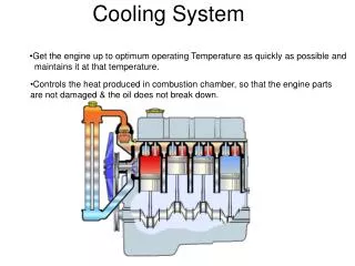
Parts of the system Basic refrigeration cycle
Parts of the system steps we followed to design the system
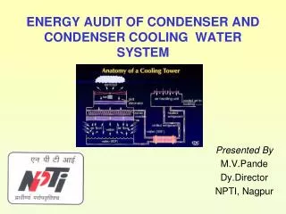
Parts of the system Heat exchanger design • How the heat exchanger reduce the power consumed by the Refrigeration cycle ? • Shell tube Heat exchanger . • Plate Heat exchanger. • Rotating wheel Heat exchanger. 21
Parts of the system Heat exchanger 22
Parts of the system Evaporator & condenser Design The main factor s affect the design are: • mean temperature difference between the fluids (K). • overall heat transfer coefficient (W/(m2 K)). • cooling capacity (W).
Parts of the system the length of evaporator 35.4 m at diameter 1cm The length of condenser 21.1 m at diameter 1cm
1 2 3 The total energy that the system need 3.018Kw 2.288 Kw compressor, 0.55 KW Fan, 0.18KW Rotating wheel more advanced research could handle Power generationand refrigerator cycle by renewable energy Parts of the system
Parts of device Design of fan
What is our goal ? Mass flow rate of air : Four levels 89 CFM 115CFM 139CFM 252CFM Depend on cooling the air from 25ºC to 17ºC
Parts of the system Heat exchanger design • Plate Heat exchanger 35
Parts of the system Heat exchanger 36
Parts of the system • Evaporator & condenser Design
Parts of the system Basic refrigeration cycle
1 2 The total energy that the system need 1.078kW 0.572 Kw compressor, 0.5 KW Fan Parts of the system
Why We design a prototype for the project wasn't in conformity with the original design • lack of some of the required pieces in the local market • Lack of • Funding &
The cooling cycle that we have used is a cycle of a normal air conditioner • so the lowest possible temperature we can get here is Whereasthe required temperature is
The original evaporator of the cycle was changed because of the Inconvenience with the design , So that reduced the circuit’s ability in refrigerating.
As a result of decreasing the cycle ability in refrigerating, we had to minimize the air flow into the cycle by using a mechanical gate which was placed on the blower’s suction instead of using an inverter –because of the high cost of the last one- in order to control the flow.
The area of the heat exchanger we have used is small and the distances between each plate and the other is large because the manufacturing capacity is limited in the market .This heat exchanger is not available in the local market as well as the required specifications , while importing from abroad is difficult due to the costs.
Heat exchanger was manufactured from tin alloy which is considered to be a low-conductivity material respect to the conductivity of the materials that the exchanger is always made from, but the selection of tin alloy was due to its low price. Unfortunately that affected the results, so we didn’t get the exact desired results.
Finally, as a result of using the centrifugal blower, we have obliged to design a duct that led to high pressure drop, and thus reduced the flow volume of 1480CFM to 252CFM, then increasing the motor burden leading to increase the consumed energy too.
Recommendation • The results that we reach were not already achieved theory, to be: • At the first, axial blower recommended using to decrease pressure drop to minimum, and the duct forms should be funnel-shaped not square shape.
On the other hand, the alloy used to manufacturing heat exchanger should be copper alloy its better than tin alloy to rise the efficiency of heat exchanging, but the rotary wheel heat exchanging is much better than the plate one, it has more efficiency and smaller size.