Download
1 / 14
140 likes | 147 Views
A float with a permanent magnet moves reliably along with the liquid level on a guide tube. Within the guide tube is fitted a reed contact (inert gas contact), which is energised, through the non-magnetic walls of the float and guide tube, by the approach of the float magnet. By using a magnet and reed contact the switching operation is non-contact, free from wear and needs no power supply. The contacts are potential-free. WIKA float switches with permanent magnets are also available with several switch points.<br>For More Information visit on:- www.seeautomation.com<br>Our Mail I.D:- sales@seeautomation.com<br>Contact Us:- 91-11-22012324 , 8144883403<br>WEB URL:-http://www.seeautomation.com/product-description/float-switches-with-permanent-magnet/326<br>

E N D
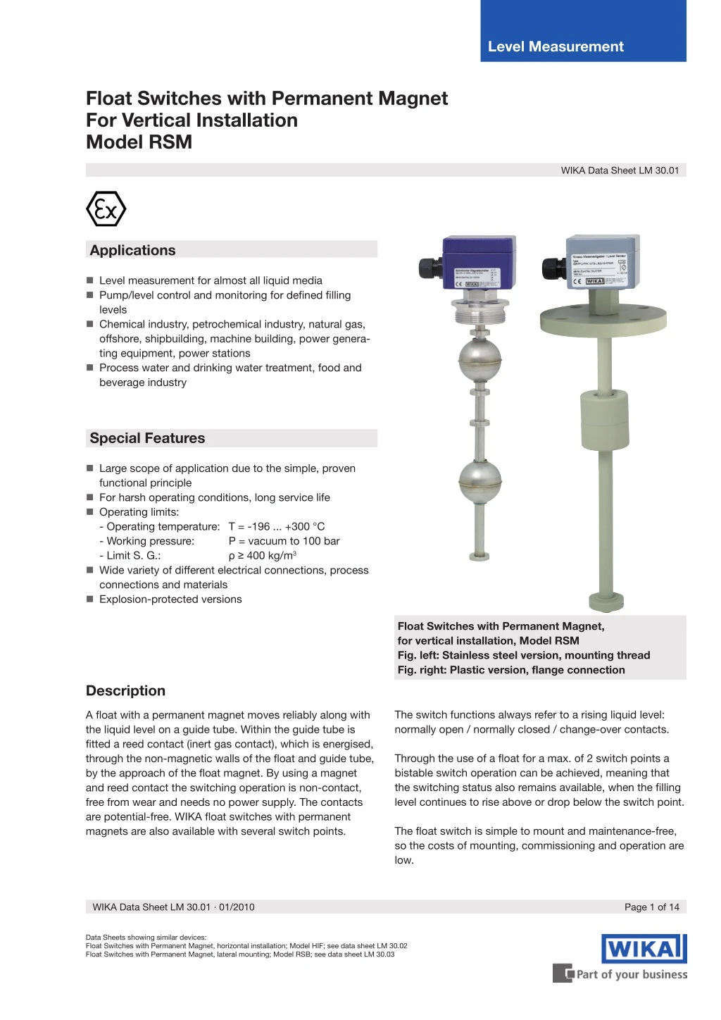
Level Measurement Float Switches with Permanent Magnet For Vertical Installation Model RSM WIKA Data Sheet LM 30.01 Applications Level measurement for almost all liquid media Pump/level control and monitoring for defined filling levels Chemical industry, petrochemical industry, natural gas, offshore, shipbuilding, machine building, power genera- ting equipment, power stations Process water and drinking water treatment, food and beverage industry Special Features Large scope of application due to the simple, proven functional principle For harsh operating conditions, long service life Operating limits: - Operating temperature: T = -196 ... +300 °C - Working pressure: - Limit S. G.: Wide variety of different electrical connections, process connections and materials Explosion-protected versions P = vacuum to 100 bar ρ ≥ 400 kg/m3 Float Switches with Permanent Magnet, for vertical installation, Model RSM Fig. left: Stainless steel version, mounting thread Fig. right: Plastic version, flange connection Description The switch functions always refer to a rising liquid level: normally open / normally closed / change-over contacts. A float with a permanent magnet moves reliably along with the liquid level on a guide tube. Within the guide tube is fitted a reed contact (inert gas contact), which is energised, through the non-magnetic walls of the float and guide tube, by the approach of the float magnet. By using a magnet and reed contact the switching operation is non-contact, free from wear and needs no power supply. The contacts are potential-free. WIKA float switches with permanent magnets are also available with several switch points. Through the use of a float for a max. of 2 switch points a bistable switch operation can be achieved, meaning that the switching status also remains available, when the filling level continues to rise above or drop below the switch point. The float switch is simple to mount and maintenance-free, so the costs of mounting, commissioning and operation are low. WIKA Data Sheet LM 30.01 ∙ 01/2010 Page 1 of 14 Data Sheets showing similar devices: Float Switches with Permanent Magnet, horizontal installation; Model HIF; see data sheet LM 30.02 Float Switches with Permanent Magnet, lateral mounting; Model RSB; see data sheet LM 30.03
Further special features Process connection, guide tube material and float made of stainless steel 1.4571 or plastic Universal signal processing: connection direct to a PLC is possible, NAMUR connec- tion, signal amplification / contact protection relays Works independently of foaming, conductivity, dielectri- city, pressure, vacuum, temperature, steam, condensati- on, blistering, boiling effects and vibrations Multiple functionality in a single instrument - up to 8 potential-free contacts Exact repeatability of the switch points Float switches with permanent magnets qualify as passive electrical equipment in accordance with DIN IEC 60 079-11 and can be installed in 'Zone 1' hazardous areas without certification, so long as the equipment is operated in a certified intrinsically safe circuit with a minimum explosion protection of EEx ib Options Customer-specific solutions Specific designs for interface layer detection ∆-ρ ≥ 50 kg / m3 Process connection, guide tube material and float made of stainless steel 1.4435, 1.4539, titanium, Hastelloy (others on request) Page 2 of 14 WIKA Data Sheet LM 30.01 ∙ 01/2010
Application examples Level switch (EEx i) Intrinsically safe Intrinsically safe Intrinsically safe relay e.g.: KR 24 Ex Intrinsically safe relay e.g.: KR 24 Ex Ex zone non Ex zone Ex zone non Ex zone Level control (min.-max. control) Contact protection relay e.g.: KR 230 Contact protection relay e.g.: KR 24 Product programme Selection of process connection, material and design ⇒ further information on the indicated pages. Process connection Material Stainless steel Explosion-protected version Material PVC / PP / PVDF Mounting thread (without terminal box) G 1/8" ... G 2" - Page 8 Page 4 Page 5 (adjustable guide tube) Page 7 (Mini float) Mounting thread G 1/2" ... G 2" Page 6 Page 8 Page 4 Page 5 (adjustable guide tube) Page 7 (Mini float) Flange DN 50 ... DN 200 PN 6 ... PN 100 Page 6 Page 8 Page 4 Page 5 (adjustable guide tube) Page 9 (E-CTFE coated) Float versions: page 10 and 11 Contact protection measures: page 12 Connection diagrams: page 13 and 14 WIKA Data Sheet LM 30.01 ∙ 01/2010 Page 3 of 14
Standard version Process connection, guide tube material and float made of stainless steel 1.4571 Terminal box Terminal box Connection cable L 1 = ... L 1 = ... L 1 = ... L = ... L = ... L = ... Mounting thread (without terminal box) Mounting thread Flange Electrical connection Connection cable PVC grey Terminal box Aluminium 64 x 58 x 34 mm, with 1 contact Aluminium 80 x 75 x 57 mm, 2 or more contacts Option: Polypropylene, polyester, stainless steel PVC blue Silicone PUR Process connection Mounting thread upwards G 3/8" (others on request) Mounting thread downwards G 1 1/2" or G 2" Mounting flange DIN DN 50 ... DN 200, PN 6 ... PN 100 ANSI 2" ... 8", Class 150 ... 600 G 1/2" (others on request) Guide tube diameter 12 or 14 mm 18 mm 12 or 14 mm 18 mm 12 or 14 mm 18 mm Guide tube lengthL max. 3000 mm 6000 mm 3000 mm 6000 mm 3000 mm 6000 mm Float Material stainless steel 1.4571 (Option: Buna, titanium) Float diameter from 44 ... 120 mm Float selection depending on guide tube diameter and process conditions (see page 10 and 11) Temperature range standard PVC / PUR cable -10 ... +80 °C Silicone cable -30 ... +150 °C Option: High temperature version: +150 ... +300 °C Option: Low temperature version: -196 ... -30 °C -30 ... +150 °C Switch function Optionally contact makes S, contact breaks O or change-over U - at increasing level Max. number of contacts PVC cable 6 x S or O, or 4 x U Silicone cable 5 x S or O, or 3 x U 6 x S or O, or 4 x U Switch position Dimensions L1, L2, L3 ... (from sealing face, starting from top) Distance between switch points Minimum 20 mm (depending on the selection of the float and the contacts, see page 10 and 11) Contact rating Contact makes 230 V AC; 100 VA; 1 A 230 V DC; 50 W; 0.5 A Contact breaks 230 V AC; 100 VA; 1 A 230 V DC; 50 W; 0.5 A Change-over 230 V AC; 40 VA; 1 A Please observe contact protection measures (see page 12)! 230 V DC; 20 W; 0.5 A Attention: Versions without protective earth conductor - operation only at safety extra-low voltage e.g. WIKA contact protection relay or external earthing Mounting position Vertical ± 30° Ingress protection IP 65 per EN 60 529 / lEC 529 Page 4 of 14 WIKA Data Sheet LM 30.01 ∙ 01/2010
Version with adjustable guide tube Process connection, guide tube material and float made of stainless steel 1.4571 Terminal box Terminal box loosening union nut loosening union nut loosening union nut adjustable by Connection cable guide tube adjustable by adjustable by guide tube guide tube 27 mm flats 27 mm flats 27 mm flats G 1/2" 14 L 1 = ... L 1 = ... L 1 = ... L = ... L = ... L = ... Mounting thread (without terminal box) Mounting thread Flange Electrical connection Connection cable PVC grey Terminal box Aluminium 64 x 58 x 34 mm, with 1 contact Aluminium 80 x 75 x 57 mm, 2 or more contacts Option: Polypropylene, polyester, stainless steel PVC blue Silicone PUR Process connection Mounting thread upwards G 1/2" (others on request) Mounting thread downwards G 1 1/2" or G 2" (others on request) Mounting flange DIN DN 50 ... DN 200, PN 6 ... PN 100 ANSI 2" ... 8", Class 150 ... 600 Guide tube diameter 12 mm Guide tube lengthL max. 3000 mm Float Material stainless steel 1.4571 (Option: Buna, titanium) Float diameter from 44 ... 83 mm Float selection depending on guide tube diameter and process conditions (see page 10 and 11) Nominal pressure 5 bar Temperature range standard PVC / PUR cable -10 ... +80 °C Silicone cable -30 ... +150 °C -30 ... +150 °C Switch function Optionally contact makes S, contact breaks O or change-over U - at increasing level Max. number of contacts PVC cable 6 x S or O, or 4 x U Silicone cable 5 x S or O, or 3 x U 6 x S or O, resp. 4 x U Switch position Dimensions L1, L2, L3 ... (from sealing face, starting from top) Distance between switch points Minimum 20 mm (depending on the selection of the float and the contacts, see page 10 and 11) Contact rating Contact makes 230 V AC; 100 VA; 1 A 230 V DC; 50 W; 0.5 A Contact breaks 230 V AC; 100 VA; 1 A 230 V DC; 50 W; 0.5 A Change-over 230 V AC; 40 VA; 1 A Please observe contact protection measures (see page 12)! 230 V DC; 20 W; 0.5 A Attention: Versions without protective earth conductor - operation only at safety extra-low voltage e.g. WIKA contact protection relay or external earthing Mounting position Vertical ± 30° Ingress protection IP 54 per EN 60 529 / lEC 529 IP 65 per EN 60 529 / lEC 529 WIKA Data Sheet LM 30.01 ∙ 01/2010 Page 5 of 14
Explosion-protected version, intrinsically safe II 1/2G EEx ia IIC T3-T6 KEMA 09 ATEX 0182X II 2D T80 °C IP6X Process connection, guide tube material and float made of stainless steel 1.4571 Terminal box Terminal box X X Process temperature Raised terminal box X 0 mm L 1 = ... L 1 = ... L = ... L = ... < 60 °C < 135 °C < 180 °C 60 mm 80 mm Mounting thread Flange Electrical connection Terminal box Aluminium 80 x 75 x 57 mm Option: Polyester, stainless steel Process connection Mounting thread downwards G 1 1/2" or G 2" (others on request) Mounting flange DIN DN 50 ... DN 150, PN 6 ... PN 64 ANSI 2" ... 6", Class 150 ... 600 Guide tube diameter 12 or 14 mm 18 mm 12 or 14 mm 18 mm Guide tube lengthL max. 3000 mm 6000 mm 3000 mm 6000 mm Float Material stainless steel 1.4571 (Option: Buna, titanium) Float diameter from 44 ... 120 mm Float selection depending on guide tube diameter and process conditions (see page 10 and 11) Temperature class Process temperature Ambient temperature at terminal box Max. T3 180 °C T4 130 °C T5 95 °C T6 80 °C Max. 60 °C 60 °C 60 °C 60 °C Switch function Optionally contact makes S, contact breaks O or change-over U - at increasing level Max. number of contacts 6 x S or O, or 4 x U Switch position Dimensions L1, L2, L3 ... (from sealing face, starting from top) Distance between switch points Minimum 20 mm (depending on the selection of the float and the contacts, see page 10 and 11) Contact rating Only for connection to a certified intrinsically safe circuit with Umax 36 V, Imax 100 mA Mounting position Vertical ± 30° Ingress protection IP 65 per EN 60 529 / lEC 529 Options Temperature resistance Pt100 or Pt1000 Bimetal thermal contact 40 ... 120 °C (in 5 degree steps) Page 6 of 14 WIKA Data Sheet LM 30.01 ∙ 01/2010
Mini float version Process connection and guide tube material made of stainless steel 1.4571 Terminal box Coupler connector ASC4 M12 x 1 Terminal box Connection cable G 1/8" 12 27 mm flats L 1 = ... L 1 = ... L 1 = ... L 1 = ... L = ... L = ... L = ... L = ... Mounting thread (without terminal box) Mounting thread Electrical connection Connection cable PVC grey Terminal box Aluminium 64 x 58 x 34 mm Coupler connector ASC4, C 164-232-F-4P Coupler connector M12 x 1 PVC blue Silicone PUR Process connection Mounting thread upwards G 1/8" (others on request) Mounting thread downwards oder G 1" (others on request) Guide tube diameter 8 mm Guide tube lengthL max. 500 mm Float Material stainless steel 1.4571 (Option: Buna, polypropylene, titanium) Float diameter from 23 ... 29 mm Float selection depending on guide tube diameter and process conditions (see page 10 and 11) Temperature range -10 ... +100 °C (Float material stainless steel or titanium) -10 ... +80 °C (Float material Buna or polypropylene) Switch function Optionally contact makes S, contact breaks O or change over U - at increasing level Max. number of contacts 3 x S or O, or 1 x U Contact rating Contact makes 250 V AC; 10 VA; 0.5 A 250 V DC; 5 W; 0.25 A Contact breaks 250 V AC; 10 VA; 0.5 A 250 V DC; 5 W; 0.25 A Change-over 28 V AC; 6 VA; 0.6 A 28 V DC; 3 W; 0.3 A Please observe contact protection measures (see page 12)! Attention: Versions without protective earth conductor - operation only at safety extra-low voltage e.g. WIKA contact protection relay or external earthing Mounting position Vertical ± 30° Ingress protection IP 54 per EN 60 529 / lEC 529 IP 65 per EN 60 529 / lEC 529 WIKA Data Sheet LM 30.01 ∙ 01/2010 Page 7 of 14
Plastic version Process connection, guide tube material and float made of PVC, polypropylene or PVDF Guide tube Ø 12 mm Connection cable G 3/8" 12 Terminal box Terminal box 22 mm flats L 1 = ... L = ... M20 x 1.5 M20 x 1.5 Guide tube Ø 16 mm Connection cable G 1/2" 14 27 mm flats L 1 = ... L 1 = ... L = ... L = ... L 1 = ... L = ... Connection cable Guide tube Ø 20 mm G 1" 24 32 mm flats L 1 = ... L = ... Mounting thread (without terminal box) Mounting thread Flange Electrical connection Connection cable PVC grey Terminal box Polypropylene 80 x 82 x 55 mm PVC blue PUR Process connection Mounting thread, upwards G 3/8" (Guide tube Ø 12 mm) G 1/2" (Guide tube Ø 16 mm) G 1" (Guide tube Ø 20 mm) (others on request) Mounting thread, downwards G 1 1/2" or G 2" (others on request) Mounting flange DIN DN 50 ... DN 125, PN 10, Form A ANSI 2" ... 5", Class 150 FF Guide tube diameter 12, 16 or 20 mm (16 and 20 mm: strengthened with a metallic inner tube) Guide tube lengthL max. 500 mm (Guide tube Ø 12 mm) 3000 mm (Guide tube Ø 16 mm) 5000 mm (Guide tube Ø 20 mm) Float Material Float diameter from 44 ... 80 mm Float selection depending on guide tube diameter and process conditions (see page 11) PVC Polypropylene PVDF Temperature range PVC Polypropylene -10 ... +80 °C PVDF 0 ... +60 °C -10 ... +100 °C Switch function Optionally contact makes S, contact breaks O or change-over U - at increasing level 4 x S or O (PP max. 3) resp. 3 x U (PP max. 2) Max. number of contacts Switch position Dimensions L1, L2, L3 ... (from sealing face, starting from top) Minimum 20 mm (depending on the selection of the float and the contacts, see page 11) Distance between switch points Contact rating Contact makes 230 V AC; 100 VA; 1 A 230 V DC; 50 W; 0.5 A Contact breaks 230 V AC; 100 VA; 1 A 230 V DC; 50 W; 0.5 A Change-over 230 V AC; 40 VA; 1 A Attention: Versions without protective earth conductor - operation only at safety extra-low voltage e.g. WIKA contact protection relay or external earthing Please observe contact protection measures (see page 12)! 230 V DC; 20 W; 0.5 A Mounting position Vertical ± 30° Ingress protection IP 54 per EN 60 529 / lEC 529 IP 65 per EN 60 529 / lEC 529 Page 8 of 14 WIKA Data Sheet LM 30.01 ∙ 01/2010
Stainless steel version, E-CTFE coated Process connection, guide tube material and float made of stainless steel 1.4571, E-CTFE coated Terminal box L 1 = ... L = ... Flange (Guide tube diameter 12 mm) Flange (Guide tube diameter 18 mm) Electrical connection Terminal box Aluminium 64 x 58 x 34 mm, with 1 contact Aluminium 80 x 75 x 57 mm, 2 or more contacts Option: Polypropylene, polyester, stainless steel Process connections Mounting flange DIN DN 50 ... DN 200, PN 6 ... PN 40 ANSI 2" ... 8", Class 150 ... 300 Guide tube diameter 12 mm 18 mm Guide tube lengthL max. 2000 mm 4000 mm Float Material stainless steel 1.4571 (E-CTFE coated) Float diameter from 45 ... 121 mm Float selection depending on guide tube diameter and process conditions (see page 10) Temperature range Depending on medium Switch function Optionally contact makes S, contact breaks O or change-over U - at increasing level Max. number of contacts 3 x S or O, resp. 2 x U Switch position Dimensions L1, L2, L3 ... (from sealing face, starting from top) Distance between switch points Minimum 20 mm (depending on the selection of the float and the contacts, see page 10) Contact rating Contact makes 230 V AC; 100 VA; 1 A 230 V DC; 50 W; 0.5 A Contact breaks 230 V AC; 100 VA; 1 A 230 V DC; 50 W; 0.5 A Change-over 230 V AC; 40 VA; 1 A Please observe contact protection measures (see page 12)! 230 V DC; 20 W; 0.5 A Attention: Versions without protective earth conductor - operation only at safety extra-low voltage e.g. WIKA contact protection relay or external earthing Mounting position Vertical ± 30° Ingress protection IP 65 per EN 60 529 / lEC 529 WIKA Data Sheet LM 30.01 ∙ 01/2010 Page 9 of 14
Spherical floats (K) Ø C D D = Limit S. G. of the medium immersed float volume 85 % E B E = Nominal S. G. of the medium immersed float volume 50 % Ø A Material Suits guide tube Ø mm Ø A mm B mm Ø C mm Max. working pressure bar Max. operating temperature °C Limit S. G. 85 % kg/m3 Nominal S. G. 50 % kg/m3 8 Stainless steel 1.4571 29 28 9 6 100 977 1660 8 29 28 9 25 100 1069 1817 12 52 52 15 40 300 769 1307 12 62 61 15 32 300 597 1015 12 83 81 15 25 300 408 693 18 80 76 23 25 300 679 1155 18 98 96 23 25 300 597 1016 18 105 103 23 25 300 533 907 18 120 117 23 25 300 389 661 8 Titanium 3.7035 29 28 9 30 100 822 1397 12 52 52 15 25 300 707 1201 12 52 52 15 60 300 852 1448 12 52 52 15 80 300 1060 1802 12 62 62 15 25 300 505 859 12 83 81 15 25 300 278 473 18 80 76 23 25 300 665 1130 18 98 96 23 25 300 495 841 18 105 103 23 25 300 369 627 18 120 117 23 25 300 329 560 12 Stainless steel 1.4571 53 53 14 25 depending on medium 745 1266 12 E-CTFE coated 63 62 14 25 depending on medium 591 1005 12 84 82 14 25 depending on medium 403 685 18 81 77 22 25 depending on medium 718 1220 18 99 97 22 25 depending on medium 675 1148 18 106 104 22 25 depending on medium 633 1076 18 121 118 22 25 depending on medium 459 781 Note: The optimum float will be selected after a feasibility test carried out by WIKA. Page 10 of 14 WIKA Data Sheet LM 30.01 ∙ 01/2010
Cylindrical floats (Z) Ø C D D = Limit S. G. of the medium immersed float volume 85 % E B E = Nominal S. G. of the medium immersed float volume 50 % Ø A Material Suits guide tube Ø mm Ø A mm B mm Ø C mm Max. working pressure bar Max. operating temperature °C Limit S. G. 85 % kg/m3 Nominal S. G. 50 % kg/m3 8 Stainless steel 1.4571 27 31 10 16 100 787 1338 12 44 52 15 16 300 818 1390 12 Titanium 3.7035 44 52 15 16 300 720 1224 8 Buna 20 20 9 3 80 939 1597 8 23 25 9 3 80 802 1364 8 25 14 9 3 80 787 1337 8 30 45 13 3 80 683 1161 12 40 30 15 3 80 581 988 12 40 120 15 3 80 409 694 18 50 45 19 3 80 498 847 12 PVC 44 44 14 3 60 651 1107 16 55 54 22 3 60 798 1357 20 55 80 26 3 60 919 1563 16 55 70 22 3 60 674 1145 20 80 79 25 3 60 573 974 8 Polypropylene 27 29 9 3 80 755 1284 8 35 33 9 3 80 675 1148 12 44 44 14 3 80 478 812 16 55 54 22 3 80 582 989 20 55 80 26 3 80 669 1137 20 80 79 25 3 80 431 732 12 PVDF 44 55 14 3 100 782 1329 16 55 69 22 3 100 821 1396 20 55 80 26 3 100 1140 1938 20 80 79 25 3 100 681 1157 Stainless steel 1.4571 E-CTFE coated depending on medium 12 45 53 14 16 782 1329 Note: The optimum float will be selected after a feasibility test carried out by WIKA. WIKA Data Sheet LM 30.01 ∙ 01/2010 Page 11 of 14
Contact protection measures To ensure reliable operation of sensors with reed switches and highest possible service life, we recommend using one of the following circuits. Surge current measurement with oscilloscope S1 Inductive load AC S1 RE C 24 V DC RC modules depending on operating voltage see table Example: R 24 - 230V AC C = 0.33 µF/24 V DC RM C Inductive load DC I (A) S1 without current limitation + not allowed 4 Shunt diode e.g. 1N4007 24 - 250V DC 3 with current limitation 2 – 1 allowed 3-10 t (? s) µ Current limitation with capacitive load e.g. PLC, DCS and cables > 50 m Protective RC modules RC modules are, depending on the operating voltage, to be used exclusively according to the table below. S1 RS + Rs = 22 Ohm (47 Ohm with 0 VA contacts) C1= internal capacitance C1 D 24 V DC SPS – D = Ø 16 mm - Ø 25 mm L = 26 mm - 58 mm L wire Current limitation with electronic timers 200 S1 RS + Rs = 220 Ohm (230 V AC) C1= internal capacitance For inert gas contacts from 10 ... 40 VA C1 230 V AC Capacitance Resistance 0.33 µF 0.33 µF 0.33 µF 0.33 µF Voltage 24 V AC 48 V AC 115 V AC 230 V AC Zeit- relais relay time 100 Ohm 220 Ohm 470 Ohm 1500 Ohm – For inert gas contacts from 40 ... 100 VA Capacitance Resistance 0.33 µF 0.33 µF 0.33 µF 0.33 µF Voltage 24 V AC 48 V AC 115 V AC 230 V AC 47 Ohm 100 Ohm 470 Ohm 1000 Ohm Other types than the RC modules specified here might lead to destruction of the reed contact. Page 12 of 14 WIKA Data Sheet LM 30.01 ∙ 01/2010
Connection diagrams Colour coding per IEC 757 PVC cable Silicone cable Terminal box Contact makes or breaks Change-over Contact makes or breaks Change-over Contact makes or breaks Change-over 1 switch point 1 switch point 1 switch point 1 switch point 1 switch point 1 switch point GY BN GY BN 1 2 GY BN GY BN BK GY BN BK GY 1 BN 2 BK 3 L1 L1 L1 L1 L1 L1 2 switch points 2 switch points 2 switch points 2 switch points 2 switch points 2 switch points BK BK BN GY BK BK BN GY BK BK BN GY 1 2 3 4 L1 L1 L1 YE GN BN BU PK GY YE GN BN GY RD WH YE 1 GN 2 BN 3 GY 4 RD 5 WH 6 L1 L1 L1 L2 L2 L2 3 switch points 3 switch points 3 switch points L2 L2 L2 GN BN YE GY PK BU BN WH YE GN GY RD BN WH YE GN GY RD 1 2 3 4 5 6 L1 L1 L1 3 switch points 3 switch points L2 L2 L2 BU/RD RD WH YE GN BN BU PK GY WH 1 BK 2 OG 3 YE 4 GN 5 BN 6 BU 7 PK 8 GY 9 L3 L3 L3 L1 L1 4 switch points 4 switch points L2 L2 RD WH GN BN YE GY PK BU RD WH GN BN YE GY PK BU 1 2 3 4 5 6 7 8 L1 L1 L2 L2 L3 L3 L3 L3 4 switch points 4 switch points L4 L4 GY/RD BK VT BU/RD RD WH YE GN BN BU PK GY WH 1 BK OG YE GN BN BU PK GY RD 10 VT 11 L1 L1 2 3 4 5 6 7 8 9 5 switch points 5 switch points BK VT RD WH GN BN YE GY PK BU RD WH GN BN YE GY PK BU VT CLEAR 10 1 2 3 4 5 6 7 8 9 L1 L1 L2 L2 L2 L2 L3 L3 L3 L3 L4 L4 L4 L4 L5 L5 CLEAR 12 6 switch points 6 switch points GY/RD BU/RD BK VT RD WH GN BN YE GY PK BU RD WH GN BN YE GY PK BU VT CLEAR 10 BK OG 1 2 3 4 5 6 7 8 9 L1 L1 L2 L2 L3 L3 L4 L4 L5 L5 11 12 L6 L6 WIKA Data Sheet LM 30.01 ∙ 01/2010 Page 13 of 14
Connection diagrams Colour coding per IEC 757 Coupler connector ASC4 Coupler connector M12 Contact makes or breaks Change-over 2 1 switch point 1 switch point 1 2 1 1 BN 3 BU L1 L1 3 4 BK 4 BK 2 3 BU 1 BN 2 switch points 2 2 4 BK 2 L1 1 BN 3 BU 1 3 L2 5 PE 4 BK Float switches with thermal contacts PVC or silicone cable or terminal box PVC cable Silicone cable or terminal box PVC cable Terminal box PVC or silicone cable or terminal box 1 Level contact 1 Thermal contact 1 Level contact 2 Thermal contacts 1 Level contact 2 Thermal contacts 1 Level contact 1 Thermal contact 1 Level contact 2 Thermal contacts 1 Level contact 2 Thermal contacts BK 1 BK 2 BN 3 GY 4 GN BN YE GY PK BU BN 1 WH 2 YE 3 GN 4 GY 5 RD 6 GY 1 RD 2 WH 3 BN 4 GN 5 BU/RD RD WH YE GN WH 1 BK 2 OG 3 GN 4 BN 5 GY 6 PK 7 L1 L1 L1 L1 L1 L1 ϑ ϑ55°C ϑ55°C ϑ ϑ55°C ϑ55°C ϑ75°C ϑ75°C ϑ75°C ϑ75°C PK GY Coupler connector ASC4 Coupler connector M12 Coupler connector M12 1 Level contact 1 Thermal contact 1 Level contact 1 Thermal contact 1 Level contact 1 Thermal contact 2 1 3 1 2 3 4 1 L1 L1 L1 2 3 4 5 ϑ ϑ ϑ Ordering information Model / Version / Electrical connection / Process connection / Guide tube diameter / Guide tube length L / Information about contact (switch function, number of switch points, switch position) / Process details (operating temperature and pressure, Limit S. G.) / Options Modifications may take place and materials specified may be replaced by others without prior notice. Specifications and dimensions given in this leaflet represent the state of engineering at the time of printing. Page 14 of 14 WIKA Data Sheet LM 30.01 ∙ 01/2010 01/2010 GB WIKA Alexander Wiegand SE & Co. KG Alexander-Wiegand-Straße 30 63911 Klingenberg/Germany Tel. (+49) 9372/132-0 Fax (+49) 9372/132-406 E-mail info@wika.de www.wika.de