Download

1 / 56
560 likes | 565 Views
Explore the role and function of sensors and actuators in robotics projects, including cameras, lasers, IMUs, sonar sensors, and more. Understand the importance of sensor intelligence and the different design philosophies. Learn about the taxonomy and classification of sensors and their performance. Gain insights into how sensors work and their applications in robotics.

E N D
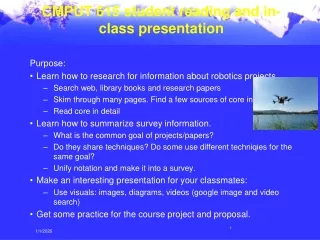
CMPUT 412 student reading and in-class presentation Purpose: • Learn how to research for information about robotics projects. • Search web, library books and research papers • Skim through many pages. Find a few sources of core info • Read core in detail • Learn how to summarize survey information. • What is the common goal of projects/papers? • Do they share techniques? Do some use different techniqies for the same goal? • Unify notation and make it into a survey. • Make an interesting presentation for your classmates: • Use visuals: images, diagrams, videos (google image and video search) • Get some practice for the course project and proposal.
CMPUT 412 student reading and in-class presentation • Presentations of robotics literature or readings projects from web pages. • The presentation is done individually. Each student books a 10 minute slot • The presentation can focus on a paper, a project web page, or be a summary of a several papers/projects. Some visuals are expected, e.g. images and videos you find on the web. • Find a title/topic, and list some sources, or give a web link to a web page you make with a source list.List not required at signup. You can add the resources as you go along • In-class presentations: Thu Feb 5, Tue Feb 19
Robotics:Sensors and Actuators Cmput412 Martin Jagersand With slides from Zach Dodds, Roland Siegwart, Csaba Szepesvári
Actuators Sensors Defining sensors and actuators Related Concepts: • Sensing -> Features -> Perception Environment Sensations (and reward) actions Controller = agent
Mobile manipulators in research • Cameras Laser range finder Cameras and 3D TOF laser Our robot CMU Herb Darpa Manip challenge
Industrial robot Underwater robot Cameras Mitsubishi PA10 McGill Aqua
Sensors on a $300 UAV Front and down facing camera • AR.Drone Ultrasonic distance (height)
BibaBot, BlueBotics SA, Switzerland Omnidirectional Camera Pan-Tilt Camera IMUInertial Measurement Unit Sonar Sensors Emergency Stop Button Laser Range Scanner Wheel Encoders Bumper
Sensor Overload? One design philosophy: • Give each sensor a specific function • Results in numerous special purpose sensors • Like a car advertized as “fully loaded” Another design philosophy: • Use a few sensors intelligently (SPA or Smart reactive) • Typically sensors with rich, detailed information e.g. • Video cameras • Laser range finders (“3D depth cameras/vision) Cameras
Many sensors might suggests reactive/subsumption One design philosophy: • Give each sensor a specific function • Results in numerous special purpose sensors • Like a car advertized as “fully loaded” • Cameras: • Go to goal • Sonars: • Follow middle corridor • Bumper: • Stop and backup if • hits a wall
Classification of Sensors • Where is the information coming from? • Inside: Proprioceptive sensors • motor speed, wheel load, heading of the robot, battery status • Outside: Exteroceptive sensors • distances to objects, intensity of the ambient light, unique features • How does it work? Requires energy emission? • No: Passive sensors • temperature probes, microphones, CCD • Yes: Active sensors • Controlled interaction -> better performance • Interference • Simple vs. composite (sonar vs. wheel sensor)
Electrical current Environment Physical process Analog to digital conversion 00101011010100 11010111010101 input output How Do (Simple) Sensors Work? Analog signals Digital signals
Sensor examples Robots’ link to the external world... sonar rangefinder Sensors, sensors, sensors! and tracking what is sensed: world models gyro compass sonar rangefinder CMU cam with on-board processing IR rangefinder odometry… Exteroceptive sensing
Tactile sensors on/off switch as a low-resolution encoder… analog input: “Active antenna” Surface acoustic waves Capacitive array sensors Resistive sensors 100% of light passes through 90% of light passes through 75% of light passes through
cyberglove Tactile applications daVinci medical system haptics Medical teletaction interfaces Robotic sensing the Zeus robotic surgeon Merritt systems, FL
Infrared sensors (1) sensing is based on light intensity. “Noncontact bump sensor” “object-sensing” IR looks for changes at this distance diffuse distance-sensing IR IR emitter/detector pair IR detector
Infrared calibration The response to white copy paper (a dull, reflective surface) raw values (put into 4 bits) inches 15º increments in the dark fluorescent light incandescent light
Infrared calibration energy vs. distance for various materials ( the incident angle is 0º, or head-on ) ( with no ambient light )
Infrared sensors (1) sensing is based on light intensity. “Noncontact bump sensor” “object-sensing” IR looks for changes at this distance diffuse distance-sensing IR (2) sensing is based on angle receved. IR emitter/detector pair
Infrared Vision frame of a robot’s IR scan of a room (in search of people…) head-tracking in an IR video
Sonar sensing sonar timeline 0 .5s 75ms the transducer goes into “receiving” mode and awaits a signal... minimum distance a “chirp” is emitted into the environment typically when reverberations from the initial chirp have stopped after a short time, the signal will be too weak to be detected time response blanking time spatial response
walls (obstacles) Sonar effects sonar Draw the range reading that the sonar will return in each case…
walls (obstacles) Sonar effects sonar Draw the range reading that the sonar will return in each case… or nothing… holding a sponge…
Sonar effects (a) Sonar providing an accurate range measurement (b-c) Lateral resolution is not very precise; the closest object in the beam’s cone provides the response (d) Specular reflections cause walls to disappear (e) Open corners produce a weak spherical wavefront (f) Closed corners measure to the corner itself because of multiple reflections --> sonar ray tracing resolution: time / space
Ultrasonic Sensor • Frequencies: 40 - 180 kHz • Sound source: piezo/electrostatic transducer • transmitter and receiver separated or not separated • Propagation: cone • opening angles around 20 to 40 degrees • regions of constant depth • segments of an arc (sphere for 3D) Typical intensity distribution of an ultrasonic sensor Piezo transducer Electrostatic transducer
Imaging with an US Issues: • Soft surfaces • Sound surfaces that are far from being perpendicular to the direction of the sound -> specular reflection a) 360° scan
Characteristics • Range: 12cm – 5 m • Accuracy: 98%-99.1% • Single sensor operating speed: 50Hz • 3m -> 20ms ->50 measurements per sec • Multiple sensors: • Cycle time->0.4sec -> 2.5Hz->limits speed of motion (collisions)
Sonar Modeling response model (Kuc) • Models the response, hR,with c = speed of sound a = diameter of sonar element t = time z = orthogonal distance a = angle of environment surface sonar reading S a o z = • Then, allow uncertainty in the model to obtain a probability: obstacle p( S | o ) chance that the sonar reading is S, given an obstacle at location o
And beyond... Sensing and perception is often limiting a robot’s performance... LIDAR Single laser range scan ~ 270 degrees LIDAR map Sick laser range finder Sick map (evidence grid) You will get "sick" of this map… how do these compare to vision? the most computationally challenging?
Heading Sensors • Heading sensors can be proprioceptive (gyroscope, inclinometer) or exteroceptive (compass). • Used to determine the robots orientation and inclination. • Allow, together with an appropriate velocity information, to integrate the movement to an position estimate. • This procedure is called dead reckoning (ship navigation)
Compass • Since over 2000 B.C. • when Chinese suspended a piece of naturally magnetite from a silk thread and used it to guide a chariot over land. • Magnetic field on earth • absolute measure for orientation. • Large variety of solutions to measure the earth magnetic field • mechanical magnetic compass • direct measure of the magnetic field (Hall-effect, magnetoresistive sensors) • Major drawback • weakness of the earth field • easily disturbed by magnetic objects or other sources • not feasible for indoor environments
Gyroscope • Heading sensors, that keep the orientation to a fixed frame • absolute measure for the heading of a mobile system. • Two categories, the mechanical and the optical gyroscopes • Mechanical Gyroscopes • Standard gyro • Rated gyro • Optical Gyroscopes • Rated gyro
Mechanical Gyroscopes • Concept: inertial properties of a fast spinning rotor • gyroscopic precession • Angular momentum associated with a spinning wheel keeps the axis of the gyroscope inertially stable. • Reactive torque t (tracking stability) is proportional to the spinning speed w, the precession speed W and the wheels inertia I. • No torque can be transmitted from the outer pivot to the wheel axis • spinning axis will therefore be space-stable • Quality: 0.1° in 6 hours • If the spinning axis is aligned with the north-south meridian, the earth’s rotation has no effect on the gyro’s horizontal axis • If it points east-west, the horizontal axis reads the earth rotation
Rate gyros • Same basic arrangement shown as regular mechanical gyros • But: gimble(s) are restrained by a torsional spring • enables to measure angular speeds instead of the orientation. • Others, more simple gyroscopes, use Coriolis forces to measure changes in heading.
Global Positioning System (GPS) (1) • Developed for military use • Recently it became accessible for commercial applications • 24 satellites (including three spares) orbiting the earth every 12 hours at a height of 20.190 km. • Four satellites are located in each of six planes inclined 55 degrees with respect to the plane of the earth’s equators • Location of any GPS receiver is determined through a time of flight measurement • Technical challenges: • Time synchronization between the individual satellites and the GPS receiver • Real time update of the exact location of the satellites • Precise measurement of the time of flight • Interferences with other signals
Ground-Based Active and Passive Beacons • Elegant way to solve the localization problem in mobile robotics • Beacons are signaling guiding devices with a precisely known position • Beacon base navigation is used since the humans started to travel • Natural beacons (landmarks) like stars, mountains or the sun • Artificial beacons like lighthouses • The recently introduced Global Positioning System (GPS) revolutionized modern navigation technology • Already one of the key sensors for outdoor mobile robotics • For indoor robots GPS is not applicable, • Your own beacons: • LED/bulbs, coils emitting magnetic field… • Drawback with the use of beacons in indoor: • Beacons require changes in the environment • Limit flexibility and adaptability to changing environments.
And beyond... Sensing and perception is often limiting a robot’s performance... LIDAR LIDAR map Sick laser range finder Sick map (evidence grid) You will get "sick" of this map… how do these compare to vision? the most computationally challenging?
Camera Vision: The ultimate sensor? A camera offers a compelling mix of promise and frustration! not only 2d information: 3d structure, surface properties, lighting conditions, object status, et al., is there somewhere! There are vision applications and algorithms throughout robotics • Computer vision has always had close ties to robotics and AI. • A quick introduction to get you thinking about using vision… visual landmarks used in robot soccer Lec6/dogFullFps...
Vision: The ultimate sensor? • Puma robot and 2 cameras + tracking and visual servoing Cam’s on robot (Eye-in-hand) Fixed cameras (Eye-to-hand) Lec6/dogFullFps... http://www.cs.cmu.edu/~coral-downloads/legged/movies/0_Research/Vision/DogFullFpsNoSound.mpg visual landmarks used in robot soccer
3d from 2d? The 3d “time-of-flight” cameras http://www.swissranger.ch/index.php http://www.advancedscientificconcepts.com
3d from 2d? The 3d “time-of-flight” camera (1) “RF-modulated optical radiation field output” (2) Reflects off the environment (3) Time-interval input measurements provides data (not time-integrated!) How does this information get used? http://www.csem.ch/detailed/p_531_3d_cam.htm