Download
1 / 21
210 likes | 355 Views
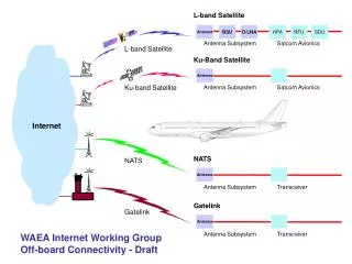
IRMS Optical Subsystem Review. The Charter. Confirm that the MOSFIRE design is a feasible baseline for IRMS (yes) Verify that the MOSFIRE design can achieve or approach the requirements of IRMS (achieves) This optical mini-study is a gateway to the next phase of the design study. Outline.

E N D
The Charter • Confirm that the MOSFIRE design is a feasible baseline for IRMS (yes) • Verify that the MOSFIRE design can achieve or approach the requirements of IRMS (achieves) • This optical mini-study is a gateway to the next phase of the design study
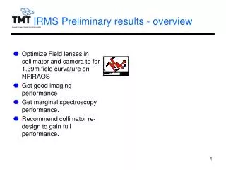
Outline • Present MOSFIRE and its components. • Describe the IRMS requirements and study scope. • Show that the MOSFIRE design is an excellent starting point, and that with tweaks can achieve IRMS requirements • I’ll show the work performed along the way
What is MOSFIRE? • Multi-Object Spectrometer for Infrared Exploration (0.97 – 2.45 µ) • A large vacuum-cryogenic instrument • At the Cass focus of Keck I: • Spectroscopy: • 6.1’ slit • Rθ ~ 2200 • Configurable slit • Imaging over ~ 6’ x 6’ FOV • ~Works in the lab
History of MOSFIRE • MOSFIRE began in July 2005, passed PDR in April 2006 and DDR one year later. • Designed to simplify as much as possible. • First light in lab July 1, 2010 • First light on Keck March 2012?
Paraxial Description of Optics Detector is 36.9 mm So the demagnification is 7.25 (f/2.00 camera)
Beam Diameter & f/# Beam Diameter [mm] Pixel Scale [as/pix] Camera Field Angle [degree] Camera f/#
MOSFIRE Rx • f/15 collimator that delivers 125.0-mm diameter pupil (f=1875 mm) • f/2 camera that delivers 0.18 arcsec/pixel (f=250 mm) • Camera has a a large pupil relief of about one focal length and operates at an amazing f/0.93 • 13 lenses + 1200 l/mm grating grating magnification of ~ 1.3
Charter • Scope as defined by TMT Statement of Work • The TMT statement of work “TMT.INS.CON.11.XXX.DRF02” (Section 2.1) is quoted below: • Verify that the results of RD2 are still valid for the as-built prescription for MOSFIRE. Confirm that, apart from modifications to the field lens and “front-end”, the remainder of the MOSFIRE design can be copied to meet the requirements of TMT/IRMS. In the event more spectrograph optics changes are needed than a small change of the field lens, the team should work with the IRMS Project Scientist to propose a design, along with ROM estimate of cost and impact, that approaches the science requirements with least perturbation of the MOSFIRE instrument. • Document and present the results of the above study to TMT Project Office, to reach agreement on any changes to the scope of the subsequent work prior to beginning that work.
Requirements (from Appendix of SoW) • Wavelength Range 0.95 – 2.49 µ • Covers a single band at a time • 80% EqE in two pixels in spectroscopy mode • 0.07” diameter images in imaging mode (allow refocus) • FOV of 2’ • Spectral and imaging sampling of 0.06” per pixel • R = 3270 with 3” slit (Rθ ~ 700 as) • YJHK produced in 6-3 order
Additional Requirements / Changes in Scope • Preconstruction design rather than as-built design • More than just changes to field lens curvature (but no major changes) • Assume that the CSU’s bars can be curved to follow the TMT focal plane • Add a pupil quality + walk requirement
Collimator • Keck delivers a 2.1-m ROC focal plane with an exit pupil 20-m away from MOSFIRE’s focal plane. • TMT/NFIRAOS Delivers a -1.3-m ROC focal plane (curved in opposite direction) and the pupil sits roughly 188-m away from IRMS’s focal plane. • Collimator focused on a 2.1-m ROC focal plane oriented in the negative direction.
The Collimator TMT Focal Surface After Reoptimization
Collimator Performance Spec is 0.07”
The Camera • Raytrace analysis in all bands with several wavelengths across a variety of spectroscopic positions. (No tracing outside of the spectroscopic field). • Using the unmodified MOSFIRE camera performance is such that the worst 1% of field/wavelength combos fall below 80% EqE. Almost all ensquared energies are above 85% • Reoptimizing the camera slightly yields 85% EqE in all fields and bands with almost all above 90%.
Additional Work • Ghost Analysis • Based on a Zemax single pass analysis • Bright detector back to instrument reflects back to detector • Only very weak ghosts, several hundred microns in diameter. • Sensitivity Analysis • Assuming MOSFIRE level misalignments the
Future Work • Talk with CSEM • Quotation on glass, polishing, and coating