Download
1 / 98
1.14k likes | 2.14k Views
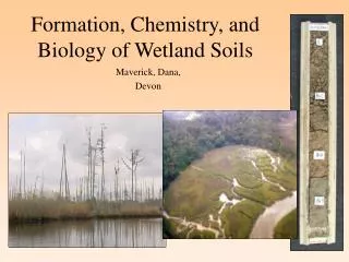
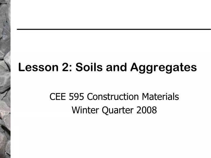
Lesson 2: Soils and Aggregates. CEE 595 Construction Materials Winter Quarter 2008. Lesson 2: Soil and Aggregate Topics. Soils Soil classification systems Soil related tests Aggregates Aggregate Production Aggregate Characterization. Soils. Laterite Soil—Brazil—Aerial View.

E N D
Lesson 2: Soils and Aggregates CEE 595 Construction Materials Winter Quarter 2008
Lesson 2: Soil and Aggregate Topics • Soils • Soil classification systems • Soil related tests • Aggregates • Aggregate Production • Aggregate Characterization
Soil Classification • Two major soil classification systems used in the US • “AASHTO” Classification (ASTM D3282, AASHTO M145) • Unified Soil Classification (USBR, 1973 and ASTM D2487) • Why classify a soil? (USBR) • Identifies and groups soils of similar engineering characteristics. • Provides a “common language” to describe soils. • In a limited manner, soil classifications can provide approximate values of engineering characteristics.
Soil Classification • How do classification systems work? • Determine gradation • Is the dominant percentage of particles larger or “granular” • Is the dominant percentage of particles “fine graded” (or silt-clay sizes). • Perform Atterberg Limit tests (more on these tests shortly).
Soil Classification—Highway Oriented System • ASTM D3282 and AASHTO M145: Classification of Soils and Soil-Aggregate Mixtures for Highway Construction Purposes. • Classification Groups split into • Granular Materials: Contains 35% or less passing the No.200 sieve. These groups generally make good to excellent subgrades. • Silt-Clay Materials: Contains more than 35% passing a No.200 sieve. These groups generally are fair to poor as subgrades.
Sieves used in ASTM D3282 and AASHTO M145 No.10 No.40 No.200
Soil Classification—Highway Oriented System • Additional tests required to perform classification grouping. • Liquid Limit (AASHTO T89, ASTM D4318): “The water content, in percent, of a soil at the arbitrarily defined boundary between the liquid and plastic states.” See next image to view the device used to determine LL. The higher the LL, the poorer the soil. • Plastic Limit (PL) and Plasticity Index (AASHTO T90, ASTM D4318): “The water content, in percent, of a soil at the boundary between the plastic and brittle states.” Plasticity Index (PI) is the “range of water content over which a soil behaves plastically.” PI = LL – PL. The higher the PI, the poorer the soil.
Soil Classification—Unified Soil Classification System • ASTM D2487: Classification of Soils for Engineering Purposes (Unified Soil Classification System) • Classification Groups split into • Coarse-grained soils: More than 50% retained on a No.200 sieve. • Fine-grained soils: 50% or more passes the No.200 sieve.
Soil Classification—Unified Soil Classification System • Coarse-grained soils: More than 50% retained on a No.200 sieve. • Gravels: More than 50% of coarse fraction retained on No.4 sieve. • Sands: 50% or more of coarse fraction passes No.4 sieve. • Fine-grained soils: 50% or more passes the No.200 sieve. • Silts and Clays: LL less than 50%. • Silts and Clays: LL 50% or more.
Unified Soil Classification System—Additional Terminology • Gravel: Particles of rock passing a 3 in. sieve but retained on a No.4 sieve. • Sand: Particles of rock passing a No.4 but retained on a No.200. • Clay: Soil passing a No.200 that exhibits plasticity (putty-like properties) within a range of water contents. Exhibits considerable strength when air dry. • Silt: Soil passing a No.200 that is nonplastic or very slightly plastic and that exhibits little or no strength when air dry.
Unified Soil Classification System • As shown in the prior image, the primary goal of this classification system is to determine the group for a specific soil (such as CL, etc.). To fully describe how this is done is too detailed for this lesson—but the process is fully described in ASTM D2487. Basically, it is a combination of sieve analyses and Atterberg Limits (LL, PL, PI). • The following table shows typical engineering characteristics associated with the Unified Soil Classification System (from USBR, 1973).
Soil Related Tests • Soil compaction • Strength or stiffness of soils • Laboratory • Field
Soil compaction • Soil compaction is the process of “artificially” increasing the density (unit weight) of a soil by compaction (by application of rolling, tamping, or vibration). • Standards are needed so that the amount of increased density needed and achieved can be measured. • Two compaction tests are commonly performed to achieve this information.
Soil Compaction: Moisture-Density Tests • Moisture-density testing as practiced today was started by R.R. Proctor in 1933. His method became known as the “standard Proctor” test. • This test (today described by ASTM D698 and AASHTO T99) applied a fixed amount of compaction energy to a soil at various water contents. Specifically, this involves dropping a 5.5 lb weight 12 inches and applying 25 “blows” per layer in 3 layers in a standard sized mold. Thus, 12,375 ft-lb per ft3 of compaction effort is applied.
Soil Compaction: Moisture-Density Tests • US Army Corps of Engineers developed “Modified Proctor” or “Modified AASHTO” to accommodate compaction needs associated with heavier aircraft used in WW 2. • ASTM D1557 and AASHTO T180: “Laboratory Compaction Characteristics of Soil Using Modified Effort (56,000 ft-lb/ft3)” • Refer to relative location of compaction curves on the next image. The higher the compaction energy, the lower the optimum water content and the higher the dry density.
Typical Compaction Curves Typical for Modified Compaction Typical for Standard Compaction Dry Density (lb/ft3) Water Content (%)
Soil Compaction—Typical Compaction Specification • Section 2-03.3(14)C, Method C: “Compacting Earth Embankments” • “Each layer of the entire embankment shall be compacted to 95 percent of the maximum density as determined by the compaction control tests described in Section 2-03.3(14)D. In the top 2 feet, horizontal layers shall not exceed 4 inches in depth before compaction. No layer below the top 2 feet shall exceed 8 inches in depth before compaction.”…. • “Under Method C, the moisture content shall not vary more than 3 percent above or below optimum determined by the tests in described in Section 2-03.3(14)D.”…. • Go to next image.
Soil Compaction—Typical Compaction Specification • Section 2-03.3(14)D: “Compaction and Moisture Control Tests” • “The maximum density and optimum moisture for materials with less than 30 percent, by mass, retained on the US No.4 sieve shall be determined …[by]… AASHTO T99.” • The are many more requirements that relate to specifying soil compaction but these two images provide a quick but focused example.
Strength or Stiffness of Soils • Typical tests of soil strength are: • Shear strength tests • Index types of tests • California Bearing Ratio (CBR) • Modulus of subgrade reaction (k) • Stabilometer Test (Hveem method) • Cone penetrometers • Resilient modulus test • CBR, R-value, cone penetrometers, and resilient modulus tests will be briefly covered.
California Bearing Ratio • The CBR test is a relative measure of shear strength for unstabilized materials and the results are stated as a percentage of a high quality crushed limestone—thus all results are shown as percentages. A CBR = 100% is near the maximum possible. CBRs of less than 10% are generally weak soils. • The test was originally developed by O. J. Porter of the California Division of Highways in 1928. The widespread use of the CBR test was created by the US Corps of Engineers during WW 2.
California Bearing Ratio • The CBR test can be reviewed in the WSDOT Pavement Guide, Module 4 (Design Parameters), Section 2 (Subgrade)--http://hotmix.ce.washington.edu/wsdot_web/index.htm • The CBR test is only conducted on unstabilized materials (soils or aggregates). • The test is most always done in the laboratory; however, a field test is available but rarely conducted.
California Bearing Ratio Test apparatus and specimen. Photo by ELE International Standard methods: ASTM D1883, AASHTO T193.
Correlations between CBR, AASHTO and Unified classification systems, the DCP, and k.
R-value • This test was developed in California by Hveem and Carmany in the late 1940’s. • In effect, it is a relative measure of stiffness since the test apparatus operates somewhat like a triaxial test. • The test is mostly used by western states for highway base and subgrade characterization. • Use of this test is likely declining a bit. • ASTM D2844 and AASHTO T190: “Resistance R-Value and Expansion Pressure of Compacted Soils”
Dynamic Cone Penetrometer (DCP) • Originally developed in the Republic of South Africa (RSA). South Africans have used and developed related tools and analyses for over 25 years. • Standard test method • ASTM D6951: “Use of the Dynamic Cone Penetrometer in Shallow Pavement Applications” • Equipment can come with different hammer weights—which can effect correlations. • Equipment can be purchased from companies such as Salem Tool Co., Salem, MI; Kessler Soils Engineering Products, Inc; or Dynatest Inc for about $1000--$2000.
Dynamic Cone Penetrometer (DCP) • Standard test method • ASTM D6951: “Use of the Dynamic Cone Penetrometer in Shallow Pavement Applications” • Equipment can come with different hammer weights: • 8 kg (17.6 lb.) • 4.6 kg (10.1 lb.) • USACE CBR—DCP correlations are contained in the ASTM standard test method (see correlations in subsequent images).
Dynamic Cone Penetrometer Positioning System Engine Mass Data Recorder Rod Reference
Semi-Automatic DCP Photos of Florida DOT equipment (June 2004). This type of DCP saves time and labor.
DCP • Examples of DCP use by the Minnesota DOT • Pavement rehabilitation strategy determination. • Locate layers in pavement structures. • Supplement foundation testing for design. • Identify weak spots in constructed embankments. • Use as an acceptance testing tool. • Location of boundaries of required subcuts.
DCP • Assumption: A correlation exists between the strength of a material and its resistance to penetration. • Typical measure is DCP Penetration Index (DPI) • Measured in mm/blow or inches/blow • Maximum depth for the DCP 800 mm • Correlations follow
DCP (if CBR > 10) Correlation • Correlation developed by the US Army Corps of Engineers (USACE) Where CBR = California Bearing Ratio (if CBR > 10) DPI = Penetration Index (mm/blow)