Download
1 / 40
490 likes | 865 Views
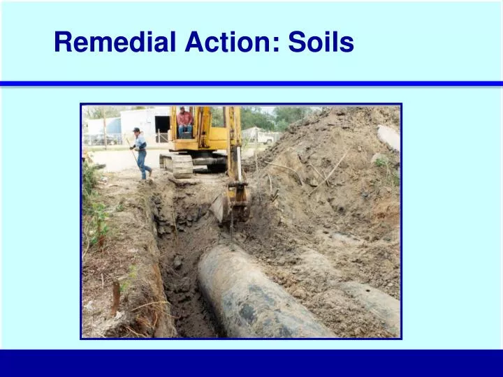
Remedial Action: Soils. Excavation and Disposal / Treatment. TREATMENT / DISPOSAL OPTIONS. Haul To Off-Site Landfill. On-Site or Off-Site Thermal Treatment. On-Site Physical / Biological Treatment. Soil Vapor Extraction. Blower or Vacuum Pump. Air / Vapor Manifold.

E N D
Excavation and Disposal / Treatment TREATMENT / DISPOSAL OPTIONS Haul To Off-Site Landfill On-Site or Off-Site Thermal Treatment On-Site Physical / Biological Treatment
Soil Vapor Extraction Blower or Vacuum Pump Air / Vapor Manifold Vapor Treatment System (Where Required) Air vacuum extracts volatile contaminants from affected soil. Clay Grout Seal Screen Sand Pack Affected Soils Water Table
Very Likely Somewhat Likely Less Likely Active Engineered Remedies Soil Vapor Extraction: Applicability COCVapor Pressure (mm Hg) Soil Air Permeability Likelihood of Success HIGH (Coarse Sand / Gravel) 104 Butane 103 102 Benzene 101 MEDIUM (Fine Sand) Xylene 100 10-1 10-2 LOW (Clay or Silt) 10-3 10-4 Aldicarb Source: CDM, 1988
Soil Vapor Extraction (SVE) System at Former Gasoline Station Vapor Treatment System SVE Wells and Collection Headers
REMOVAL / TREATMENT OPTIONS CONTAINMENT OPTIONS GW INGESTION Affected Soil Affected Groundwater GW Remediation Options GW Pump & Treat Air Sparging Dual Phase Extraction Hydraulic Containment (pumping) Barrier Walls
GW Pump & Treat: Overview Use continuous GW extraction to reduce COC concentrations in GW to applicable target levels. GOAL Moderate-to-high permeability groundwater units (K > 10-4 cm/s), low COC concentrations (CRF < 100), and no NAPL plume. APPLICABILITY NAPL GW Extraction:Recovery wells / submersible pumps; wellpoint systems. GW Treatment:GAC, air stripper, biological, etc. DESIGNOPTIONS CRF = COC Reduction Factor = (Current COC Conc./Target Level); K = Hydraulic Conductivity (cm/s) COC = Chemical of Concern
GW Pump & Treat: Well Installation Recovery Well Installation Well Screen Centralizer Wire-Wrapped Well Screen Sand-Gravel Filter Pack
Casing GW Pump & Treat: Recovery Well Design Material: Corrosion & contaminant resistant. Options = PVC, SS, teflon, FRP. Large enough to fit pump, usually 4-in or 6-in. FRP = Fiberglass reinforced plastic PVC = Polyvinyl chloride SS = Stainless steel
Well Screen GW Pump & Treat: Recovery Well Design Material: Typically same as casing. May use SS screen with PVC casing to economize. Length: 30-50% of saturated thickness for unconfined unit; 70-80% of saturated thickness for confined unit Placement: Adjust to match plume thickness, floating or sinking plume. Diameter: Prevent excessive head loss through screen by evaluating screen open area and pumping rate. Slot Size: Retain 90% of sand pack, slot size ≥ D10 of sand pack. PVC = Polyvinyl chloride SS = Stainless steel
Sand Pack Grout Seal GW Pump & Treat: Recovery Well Design Purpose: Stabilize formation, minimize fines in well, & maximize screen slot size. Thickness: 3-8 in thickness between well screen and borehole wall. Material: Clean, uniform, silica sand/gravel. Material: Portland cement/bentonite mix. Configuration: At ground surface, sloped to drain rainwater away from well casing.
Dual-Phase Extraction: Overview Use aquifer dewatering and soil venting to reduce COC concentrations in GW to applicable target levels. GOAL Low to moderate permeability groundwater units (K = 10-5 to 10-3 cm/s) APPLICABILITY GW Extraction:Recovery wells / submersible pumps; wellpoint systems. Vapor Extraction: Blower, dual phase wellpoint pump. Water Treatment: GAC, airstripper, biological Vapor Treatment, GAC, catalytic furnace. vapor GW DESIGNOPTIONS vapor Pump GW
Dual-phase pump extracts both air and water Air GW Dual-Phase Extraction: Design Options Separate Air & Water Headers:Equip each well with submersible pump. Run SVE vacuum header to each wellhead. Combined Air/ Water Header:Use dual-phase air/water vacuum pump and run single suction header to each wellhead with drop tube to water.
Air Air Sparging: Overview Inject air to volatilize organics and promote in-situ biodegradation, as needed to reduce COCs in GW to applicable target levels. GOAL Moderate to high-permeability GW units (K > 10-4 cm/s) APPLICABILITY Air Injection:Air compressor with multiple small injection points. Vapor Recovery:If needed, use SVE wells to recover and treat vapors. DESIGNOPTIONS
Air Injection Points Air Sparging: Design Issues • Well Configuration • Injection Points: 1-2 inch diam. PVC Wells, 2-5 ft Screen length • Typical Spacing: 5 - 20 ft centers • Injection Pressure: 1-10 psig • Air Flowrates • < 10 SCFM per well • Helps to Cycle injection periods (Hours, Not Days)
Air Air Sparging: Process Review Remediation Processes Volatilization of NAPLs Air Stripping of Dissolved Organics Oxygenation of Water Enhances In-Situ Biodegradation Limitations Effectiveness may be reduced if a few small channels are formed Very sensitive to heterogeneities If air flow from top of screen only, entire groundwater bearing unit not treated
O2 O2 O2 In-Situ Biodegradation: Overview Oxygen Release Compound (ORC) Solid magnesium peroxide compound activated by moisture to slowly release O2 to GW. Can achieve higher dissolved O2 levels than air sparging, theoretically. Inject ORC into aquifer or place in monitoring wells. Requires moderate GW pHlevels (e.g., pH 6-9). Applicable if GW plume notexpanding & aggressivetreatment not needed tomeet remediation goals. WHAT HOW WHEN
slurry wall Affected GW zone GW Containment: Overview Use physical or hydraulic barrier system to prevent migration of affected GW to point of exposure. GOAL Applicable to all GW units and COCs. Physical barrier walls limited to 100 ft depth. Hydraulic containment (P&T) limited by water treatment requirements. APPLICABILITY Physical Barrier:Slurry wall, asphalt wall Hydraulic Barrier:GW P&T system, cut-off trench DESIGNOPTIONS
GW Containment: Hydraulic Containment PLAN VIEW GW Pumping Well Streamlines GW Flow Plume Hydraulic Capture Zone nDesign Methods- Javendahl Capture Zone Curves nComputer Models nOperational Factors- Well Efficiency - Seasonal / Annual Effects- Produced Water Treatment
Purpose Prevent Migration of COCs from Affected Zone Reduce Inflow of Clean Groundwater Design Partial vs. Complete Enclosures Can be Keyed Into Underlining Confining Unit Construction Routinely Installed Down to 50 feet Cost: ~ $ 5 per sq. ft. for Slurry Wall slurry wall Affected GW zone GW Containment: Physical Barriers
Well Slurry Wall 0’ Slurry Wall P i s t Frac. Clay 35’ Aquifers Unfract. Clay D N A P L Drinking Water Aquifer 70’ GW Containment: Physical Barrier Hydraulic Containment by Slurry Wall
Permeable Reaction Walls Ref: Gillham Gate: Permeable Reaction Wall - Fill With Iron Filings Funnel: Impermeable Barrier Wall Funnel: Impermeable Barrier Wall Funnels Dissolved Organics Through Reaction Wall
Today’s Focus NAPL Removal Options NAPL IN UNSAT. SOIL ZONE Soil Excavation SVE NAPL IN GW ZONE NAPL in Soil Soil Excavation (smear zone) Continuous Recovery Periodic Recovery (bailing, High-Vac) Air Sparging NAPL in GW Dissolved GW Plume
NAPL Removal Options: Key Factors Key Factors Influencing NAPL Removal nVertical distribution of NAPL nPermeability of soil to NAPL nRelative soil permeability to water & NAPL
NAPL Removal Options: Vertical NAPL Distribution Well 700 600 KEY POINT: NAPL concentrates in “smear zone” atop GW table. 500 Elevation Above Oil/Water Interface (cm) 400 NAPL 300 200 100 0 H2O 0.0 0.1 0.2 0.3 0.4 0.5 0.6 0.7 0.8 0.9 1.0 Hydrocarbon Saturations NAPL = Non-aqueous phase liquid.
S i l t y S a n d ( K = 0 . 4 m / d ) s a t F i n e / M e d S a n d ( K = 4 m / d a t s r n 3 C o a s e S a d ( K = 4 m / d ) s a t NAPL Removal Options: Effects of Soil Type Soil Type vs. Permeability of Soil to NAPL 500 S i l t ( K = 0 . 1 m / d ) s a t KEY POINT: NAPL easier to remove in coarse-grained dry soils.Hard to remove in fine-grained wet soils. 400 ) 300 Elevation Above Oil/Water Interface (cm) 200 100 0 - 9 - 8 - 7 - 6 - 5 - 4 - 3 - 2 - 1 0 1 2 1 0 1 0 1 0 1 0 1 0 1 0 1 0 1 0 1 0 1 0 1 0 1 0 Hydraulic Conductivity of Soil to NAPL (m/day) Source: Beckett & Huntley, 1999 NAPL = Non-aqueous phase liquid.
1 Irreducible Water Saturation 0.8 0.6 Soil K for NAPL 0.4 Soil K for Water 0.2 0 0 0.2 0.4 0.6 0.8 1 Water Saturation of Soil Relative Permeabilities of Soil to Water & NAPL NAPL Removal Options: Relative Permeabilities KEY POINT: Soil saturated with waterhas low permeability for NAPL, so NAPL easierto removefrom dry soil. Relative Permeability
Continuous NAPL Recovery Methods Continuously recover NAPL to reduce source mass, stabilize NAPL plume (e.g., daily operation). GOAL Sites with significant mobile NAPL plume atop GW (e.g., >> 1 ft thick). APPLICABILITY Recovery wells & skimmer pumps Interceptor trench &skimmer pump Multi-phase recovery system NAPL DESIGNOPTIONS NAPL Pump
Multi-Phase NAPL Recovery Groundwater and NAPL Soil Vapor Remediated Through Air Flow Smear Zone Dewatered
May be effective in low to moderate permeability settings. Fast where It works: 2 months to 2 years. Vapor and GW treatment can be very expensive. Will not achieve low cleanup levels in groundwater. Can be impossible to dewater smear zone in certain hydrogeologic setting NAPL Removal Options Multi-Phase Recovery: Wrap-Up PRO CON
Periodic NAPL Recovery Methods Remove periodic accumulation of NAPL from observation wells to reduce NAPL mass and mobility (e.g., weekly to quarterly operation). GOAL Sites with minor NAPL accumulations and/or non-mobile NAPL plumes. APPLICABILITY Periodic bailing of wells Periodic skimmer pump operation in wells or trench. Periodic High-Vac recovery Bailer DESIGNOPTIONS NAPL
Vacuum Truck Periodic NAPL Recovery: High-Vacuum Two-Phase Flow discharge clean air Vacuum Gauge Atmospheric Air Bleed Valve NAPL / GW Collection Vapor Treatment Suction Pipe Soil Vapor Flow Conduct periodic vacuum extraction to recover NAPL (e.g., monthly or quarterly for 8-hour episode). Operational Water Table Saturated Zone GW and NAPL Flow
Remedial Action: Groundwater Groundwater /NAPL P&T System Fluid Separation Tank Recovery Well Control Panel Vapor Control System Vacuum Pump
Air NAPL Air Sparging of NAPL Plume Remove NAPL smear zone by means of in-situ “air stripping.” GOAL Sites with minor NAPL accumulations of volatile NAPL material in coarse-grained soils. APPLICABILITY Air Sparging:Periodically inject air to volatilize NAPL. DESIGNOPTIONS
Air Sparging System Blower Air Compressor Vapor Treatment SVE Well(Optional) Affected GW zone Tiny Bubbles Volatilizes Organics and Promotes In-Situ Biodeg.
Water Table Smear Zone Air Channels Silt Air pathways affected by subsurface heterogeneities. Can result in inconsistent removal. KEYPOINT: Air Sparging of NAPL Plume
No COCs > target levels Active Remediation Technologies Remedy Completion: When is “Enough” Enough? Target Levels Achieved: COC levels reduced to applicable target levels in all media. Compliance Monitoring: Follow-up monitoring (if needed) confirms remedy completion. Institutional Controls: If needed. institutional controls in place. No Further Action Required If: