Download
1 / 10
100 likes | 105 Views
This presentation discusses the mechanical status of the ECAL, specifically the opening plan for the full end-cap ECAL. It covers the weight and structure of the ECAL modules, as well as the design and analysis of the alveolar structure. Issues such as dead zones, fastening systems, thermal cooling, and connectors are also addressed. Thermal analysis and cooling technologies are discussed, as well as the design and fabrication of the detector slab. The EUDET demonstrator and R&D prototypes are also mentioned.

E N D
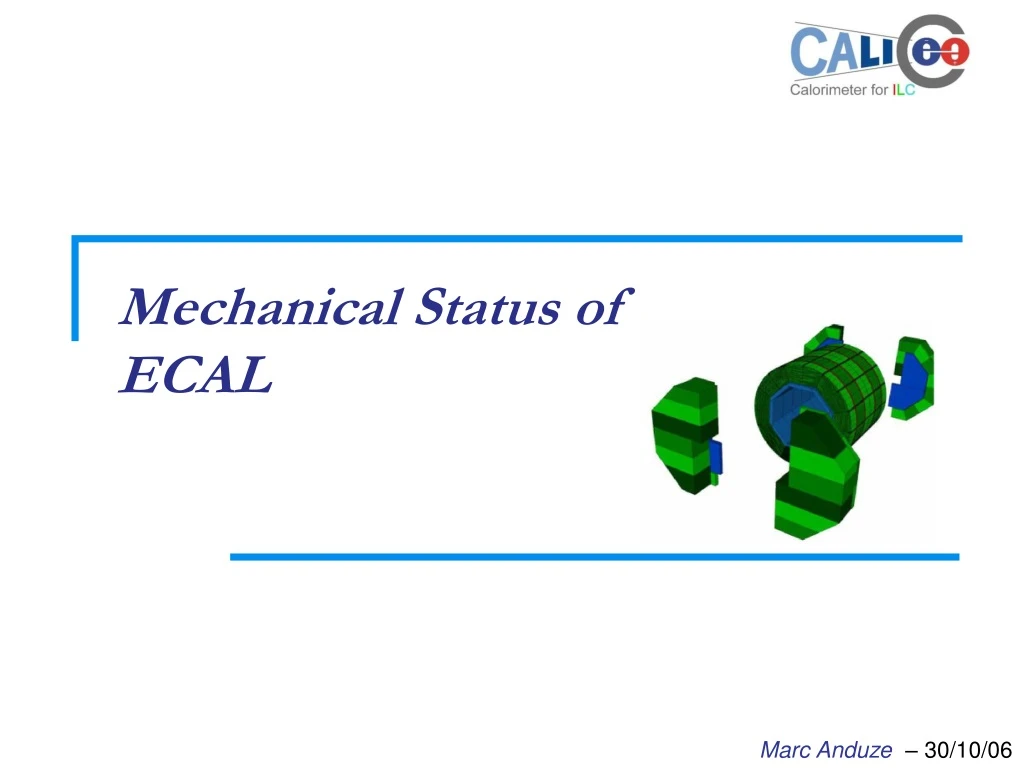
Mechanical Status ofECAL Marc Anduze– 30/10/06
Opening plan for full End-Cap ECAL - Global presentation • W/Si calorimeter (24 X0 with 29 W layers) Weight full ECAL: ~ 112 T (80 barrel+32 End-Cap) • Barrel: 40 identical trapezoidal modules • End-Cap : constituted of 12 modules (3 types) • ECAL module : alveolar structure - carbone fibers compound including half of W plates (fixed on HCAL End-Cap with rails) Minimization of dead zones • Detection elements (detector slab) in each alveolar case (Si+W), FE chips integrated, pad size : 5×5 mm2 1794 Multi-module End-Cap Barrel module 180 1600 840 Détecteur SLAB
ECAL - Alveolar structure design Linear Analysis • Global simulations : global displacements and localization of high stress zone for different solutions (definition of dimensions) • Local simulations : more precise simulations and study of different local parameters to design each part of theses structures Main ISSUES : • Dead zones : thickness of main composite sheets • Fastening system :choice of fasteners(metal inserts, rails…) • Thermal cooling (active or passive ?) • Connectors ? Configuration 0° (Nodal displacements) g Barrel module Configuration 90° Configuration 0° Configuration 90° g g g End-Cap module
g ECAL/HCAL Configuration 0° TSAI-HILL ECAL/HCAL Configuration 0° ECAL/HCAL - Interface Fastening system ECAL/HCAL is fundamental for mechanical and thermal calculations (barrel and End-Caps): • choice of fasteners : rails directly inside composite or metal inserts ? • Connections set path in gap between ECAL and HCAL (via a panel for cabling interface ?) • Rails are 1 way for positioning system (gravity support) but a second complementary system may be added for fast interchange of modules… recommendation ? • Whole End-Cap (ECAL+HCAL) assembly behavior HCAL Barrel ECAL ≤ 3 cm Only 3cm available ? HCAL ECAL
ECAL - Thermal analysis • Thermal analysis for interaction on FE ships Thermal sources: 21.8 M CALICE ECAL: ~ 82.2 M of channels Assuming that the chip power is 25 µW/channel total power to dissipate will be : 2055 W external cooling OK inside each slab :necessity of cooling system but active or passive ?Ex:Pessimist simulation of heat conduction just by the heat shield : λ = 400 W/m/K (copper) ; S = 124*0,4 mm2L = 1,55 m ; = 50* chip = 0,18 W We can estimate the temperature difference along the slab layer around 7°C and without contribution of all material from slab (PCB, tungsten, carbon fibers…)passive cooling OK ?
ECAL - Coolingtechnology • Externalcooling location: for each module, on the front end, by pipes running in the space between ECAL and HCAL. Unfortunately, in the same space we will find all the slab‘s output/input. example Cooling fans deported Heat pipes (Ø2mm) Slab’s front-end • Nearly all heat generated by the chips will go to slab’s front-end. Then, some cooling option can be foreseen: • Thermal conductors (heat shield) can be added in the slab to carry heat more efficiently along the slab direction. • Thermal cooling inside : by the way of heat pipes connected to cooling fans deported ; increase the thickness of slab.
EUDET Demonstrator - Presentation Concept : to be the most representative of the final detector module : • A alveolar composite/tungsten structure with : - same radiator sampling : 20 layers with 2.1 mm thick9 layers with 4.2 mm thick - 3 columns of cells to have representative cells in the middle of the structure (with thin composite sheets ) - Identical global dimensions (1.5m long) and shape (trapezoidal) - fastening system ECAL/HCAL (included in the design of composite structure) • 15 Detector slabs with FE chips integrated - 1 long and complete slab (L=1.5m) - 14 short slabs to obtain a complete tower of detection (typ. L=30 cm?) and design of compact outlet.
EUDET - Detector slab (1) shielding: 100 µm (cooling ?) Cables + packaging: 1000 µm PCB: 600 µm glue: 100 µm (ƒ pads size) wafer: 300 µm ground foil: 50 µm v.1 Design SLAB Main ISSUES : Front End chips inside : Thermal dissipation (cooling ?) Chip behaviour in an electron shower • Long structure : Design and fabrication problems (composite with segmentation of W plates, mechanical behaviour …) Segmentation of PCB (design of an interconnection) • Diminution of the pads size Increases of the number of channels (thermal cooling ?) Size of glue dots Epoxy protection ? (cooling ?) Heat shield: 100+400 µm (copper) Chip without packaging PCB: 800 µm glue: 100 µm (needs tests) 6500 µm wafer: 300 µm ground foil: 100 µm v.2 Design SLAB
EUDET - Detector slab (2) Connection between 2 PCB “end” PCB 7 “unit” PCB Exploded view Chip « inside »
R&D – Techno. prototypes (2006-2007) • Long Type H structures: • Design and fabrication of the long mould – (end of 2006) • Fabrication of validation model (1-3 samples ) • module EUDET: - 1.5 m long ; ≈ 500 Kg - real radiator sampling : 20 layers with 2.1 mm thick 9 layers with 4.2 mm thick • Design (mechanical and thermal simulations) of the module • Optimization of composite sheets : studies of main parameters (thickness, shape ...) • Fastening system on HCAL : design and destructive tests too • Design and fabrication of the mould with an industrial expertise (DDL consultants) • Transport tools • Fabrication of the structure (end 2007) • Mechanical support for beam test in 2008