Download
1 / 15
150 likes | 254 Views
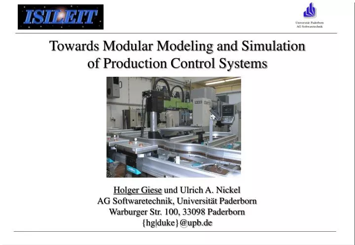
Towards Modular Modeling and Simulation of Production Control Systems. Holger Giese und Ulrich A. Nickel AG Softwaretechnik, Universität Paderborn Warburger Str. 100, 33098 Paderborn {hg|duke}@upb.de. Overview. Production Control System Executable UML Class Model & Simulation

E N D
Towards Modular Modeling and Simulation of Production Control Systems Holger Giese und Ulrich A. Nickel AG Softwaretechnik, Universität Paderborn Warburger Str. 100, 33098 Paderborn {hg|duke}@upb.de
Overview • Production Control System • Executable UML Class Model & Simulation • Modularity & Separation for Executable Models • Requirements & Simulation • Conclusion & Future Work
Flexible distributed control is „complex” to build Frequent adaptation to new requirements or changes in the topology are required Programming languages (Ada, C, …) Test & code corrections in the production environment Design and maintenance Methodology & UML Avoid long downtimes Verification is hard problem Simulation Production Control System (PCS)
PCS: Overview & Elements S ID St M S Sensors/Actors Processor Nodes ID Identification Unit Data Links St Stopper Travel Direction M Motor Signal Direction S Sensor Application SoftwareGate Bus Interface
UML Model describes: possible system topology Reactive overall class behavior (Statecharts, SDL,..) Advantages: OO concepts: e.g., class encapsulation Visual modeling High level view Track Gate Signal Executable UML Class Model
Executable UML Model Simulation Simulation Visuali-zation Production-order Code synthesis Specification Control software Dobs Simulation kernel Java Reflect Hardwareconfiguration Java Virtual Machine Topology
Simulation result: Can detect coordination problems: deadlock, … Provides insight into system dynamics (tinkering style) Limitations: System has to be complete (closed) Observations do only hold for very restricted form of subclass refinement Classes & Simulation
Component Spec.: overall behavior arbitrary structures Abstraction: combine processes build abstract process behavior for layer C depends on (A || B) no abstraction barrier for used layers Limitations: State explosion problem (propability for error detection) Component exchange preserve results only when very restricted conformance realtion holds Modularity: Overall Synchronization A C B Layer C
Reduce class behavior to external visible/relevant contract behavior Multiple contracts (UML-RT ports) Modularity: Contract
Component Spec.: set of contract behavior layered structures Abstraction: specification for layer C is C1 || ... || C4 partial model simulation & analysis arbitrary usage of provided contracts C5 || C6 || C7 assumed for used contracts Limitation: embedding restricted to layered structures Modularity: Partial Contract Border C1 C7 C2 C6 C3 C5 C4 Layer C Contracts are design elements, but the by abstraction steps derived abstract processes are not!!
Factory as open system with in and out contracts (ports): possible Environments? embedding? Modularity: Open PCS
support even for set of contract behavior and implicit dependencies Embedding only restricted by demand to ensure acyclic dependencies Abstraction: specification for C1, …, C4 Advantage: More flexible embedding when independent Modularity: Implicit Component Behavior C1 C7 C2 C6 C3 C5 C4 Component C
Open factory with implicit component behavior: implicit environment embedding rule: “depend has to remain acyclic” Modularity: Implicit Component Behavior
Requirements are described Scenario-oriented: external view system may realize suitable interleaving for multiple parallel requested tasks Factory Simulation: use for checking use for run-time assertions Requirements & Simulation
Conclusion & Future Work Modeling PCS: • strong requirements for control software • methodology & UML-RT • code synthesis and simulation (partial) Validation via simulation: • early failure detection • interactive “testing” Modular simulation • improved separation • modularity & scalability • Future Work • Realize extended concept • Integrate time support